Engineering Solutions

Color Settings

Color Settings

Previous topic Next topic Expand/collapse all hidden text  

Color Settings

Previous topic Next topic JavaScript is required for expanding text JavaScript is required for the print function  

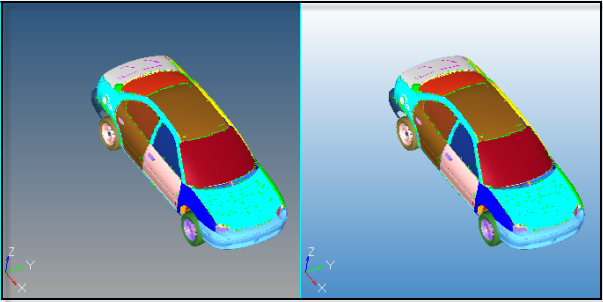
In the Colors dialog specify the colors you wish to use for various elements of the Graphical User Interface (GUI), as well as for different types of geometry and mesh entities. The Color dialog is divided into three tabs:

hmtoggle_plus1greyGeneral

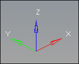
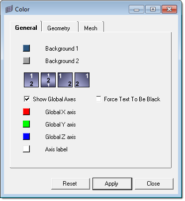
In the General tab, adjust display features in the graphics area.

Select any colors for Background 1 and Background 2, which control the color of the background gradient in the graphics area.

gradient_color_example


Select one of the gradient boxes to change the direction and style of the gradient in the graphics area. The boxes themselves illustrate the gradient pattern that they apply, but not the current colors.


Change the display of the global axes, located in the bottom corner of the graphics area.

Turn the display of the global axes on and off in the graphics area. By default, the global axes is turned on. To turn its display off, clear the Show Global Axes check box.
Change the colors of the X, Y, and Z global axis vectors. By default, the X axis is red, the y axis is green, and the Z axis is blue.
Change the color of the axis labels. By default, the axis labels are white.

global_axes


Select the Force Text To Be Black check box to change the color of all the text and lines that displays in the graphics area to be black. By default, the text is white.


hm_preferences_color_dialog


hmtoggle_plus1greyGeometry

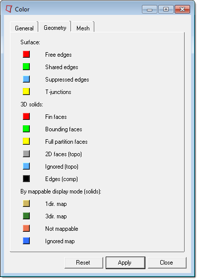
In the Geometry tab, set the colors used to display a wide range of geometric entities.

hm_preferences_color_dialog_geometrytab

Different types of geometric features are broken down first by dimensionality (2D surfaces, 3D solids), each having no influence on the geometry of the other type. A third category, By mappable display mode (solids), applies to qualities of solids rather than parts of them. These colors apply specifically to how many possible directions solids can be mapped in, and are specific to the mappable geometry display mode. They will not show in any other display mode, even if the model contains solid entities.


Surface data

Free edges

Edges of surfaces that do not connect to any other surfaces.

Shared edges

Edges of surfaces that connect to one other surface.

Suppressed edges

Shared edges that have been manually suppressed so that the automesher treats the shared surfaces as if they were one surface, allowing elements to cross the edge as if it were not there at all.

T-junctions

Edges shared by 3 or more surfaces.


3D solids

Fin faces

Surfaces that split a 3D solid entity, but only partway through. They do not actually extend through the entire entity.

Bounding faces

The outer faces of solid entities.

Full partition faces

The faces of adjoined solids.

2D faces (topo)

When using the by 2D topo visualization mode, this is the color of 2D faces that are not part of a solid.

Ignored (topo)

The color of 2D faces when using the by 2D topo visualization mode.

Edges (comp)

Mesh edges when coloring mesh with the by comp visualization mode.


By mappable display control (solids)

1 dir. map

Visualization for solids that can be mapped (for 3D meshing) in one direction.

3 dir. map

Visualization for solids that can be mapped (for 3D meshing) in three directions.

Not mappable

Visualization for solids that have been edited, but still require further partitioning to create mappable solids.

Ignored map

Default visualization for solids that require partitioning to become mappable.


hmtoggle_plus1greyMesh

In the Mesh tab, set the colors used to display a wide range of geometric entities.


Mesh line

Specify the color of the lines on a mesh that indicate the edges of mesh elements. By default, mesh line is set to auto, which assigns the component color as the mesh line color. To select a custom mesh line color for the entire mesh, click the toggle.

This option only works when the element color mode is set to By Comp. Other element color modes render mesh lines black or use the defaults selected in the Options panel, Color subpanel or in the Colors dialog, Mesh tab (accessed from the Preferences menu).

These settings are not applicable to 2nd order elements and clipped elements of section cuts, or when you are in Automesh panel mode.

Used in conjunction with the Mesh Appearance settings.


Elems, no prop/mat

Specify the color for elements that do not currently have any properties or materials assigned to them, either directly or inherited from the collectors that they belong to.


See Also:

Mesh Appearance Settings