|
»Click here to display Table of Contents«
|

Connection Manager |

|

|

|

|
|
Connection Manager |
|
|
|

|
|
»Click here to display Table of Contents«
|
Connection Manager |
|
|
|
|
|
Connection Manager |
|
|
|
|
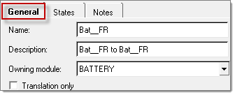
Connection properties can be defined by right-clicking on a connector in the Connector browser and selecting Manage Connection. This opens the Connection Manager tab. Three sub-tabs are available: General, States and Notes.
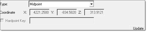
In the Location information section, a connection location type can be defined by selecting one of the options from the pull-down menu: Point A, Point B, Midpoint, or a Custom Location. When Custom Location is selected, the location can be defined either by specifying a specific coordinate, or by mapping it to a Hardpoint location.
Information related to Connected Points and distance between them is displayed in the next section. You can modify any connecting tagpoint by clicking the ![]() icon next to its label, which opens the Tagpoint Selection tool. You can then select a module first in the Module pull-down list, select a tagpoint owned by the module, or click the
icon next to its label, which opens the Tagpoint Selection tool. You can then select a module first in the Module pull-down list, select a tagpoint owned by the module, or click the ![]() icon and pick a tagpoint on the screen in the 3D graphics window and then click Select. The tagpoint list can be further filtered by clicking the
icon and pick a tagpoint on the screen in the 3D graphics window and then click Select. The tagpoint list can be further filtered by clicking the ![]() icon and selecting one of the tagpoint types: Response, Connection, Input, Plot or All (default).
icon and selecting one of the tagpoint types: Response, Connection, Input, Plot or All (default).
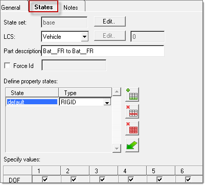
When checked, the Switch Nodes check box allows you to change the independent node from Point A to Point B, based on their dependency status, to avoid an already dependent node being specified as dependent again when the connection is realized into new rigid elements. Connection properties are defined in the State tab of the Connection Manager.
State set is designed to capture a unique hardware part with its own set of connection properties (for example, hydromount vs. a base rubber part). By default, a base State set is already created and assigned to the connector. Therefore, unless there is a need for multiple sets of properties, the default base State set selection does not need to be changed.
State sets can be added by clicking the ![]() icon, or deleted by clicking the
icon, or deleted by clicking the ![]() icon. You can double-click a State set to edit its name and click Select to finalize the selection.
icon. You can double-click a State set to edit its name and click Select to finalize the selection.
The LCS drop-down menu provides four options for specifying coordinate systems used by any element generated during connection realization:
| • | Vehicle: ‘0’ or the basic coordinate system is used. |
| • | Owned: This option allows you to create a custom LCS by clicking Edit. |
| • | TagPointA: Local coordinate system specified as the output Displacement Coordinate System on the grid card associated when TagPointA is used. |
| • | TagPointB: Local coordinate system specified as the output Displacement Coordinate System on the grid card associated when TagPointB is used. |
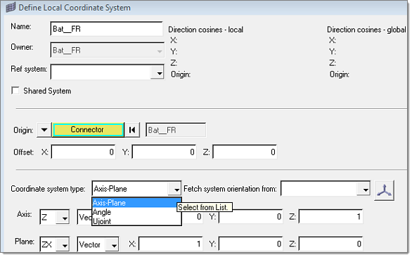
When the Owned local coordinate system is selected, a local coordinate system managed in the assembly can be created using the Define Local Coordinate System dialog. Three types of coordinate systems can be defined:
| • | Axis-Plane: Two vectors are required to define this system. A vector can either be specified in direction cosines, or by selecting two tagpoints. |
| • | Angle: Any combinations of angle rotations around the reference axes can be used to define this system. |
| • | Ujoint: The Ujoint coordinate systems is defined by selecting two tagpoints on the input shaft and two tagpoints on the output shaft. A homo-kenetic coordinate system will then be created to properly describe motion transfer of Ujoints from the input to the output shafts. |
Force Id: For connectors gives you an option to define the numbering pattern to a connector, so that the connection elements created by realization of those connectors fall in the defined numbering pattern.
Five options are available in specifying property states, as shown in the image below:
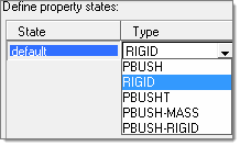
| • | PBUSH – A CBUSH element is generated during connection realization. The PBUSH card allows you to specify K (stiffness), B (viscous damping), GE (material damping), M (mass and moment of Inertia) and RIGID (check boxes for rigidly connected DOFs.) Note: The M and RIGID fields are not supported in the Nastran profile and are ignored. |
| • | RIGID – A RBE2 element with DOFs specified in checked boxes is generated during connection realization. |
| • | PBUSHT – A CBUSH element is generated during connection realization. In addition to the PBUSH card that specifies the base properties, a PBUSHT card allows you to specify frequency tables for K, B and GE. |
| • | PBUSH-MASS – A CBUSH element with two COMN2 elements at its Point A and Point B are generated during connection realization. Note: This type is designed to be used in the Nastran profile where the M fields for PBUSH are not supported by the Nastran solver. |
| • | PBUSH-RIGID – A CBUSH element with a parallel RBE2 element are generated during connection realization. Note: This type is designed to be used in the Nastran profile where the RIGID check boxes for PBUSH are not supported by the Nastran solver. |
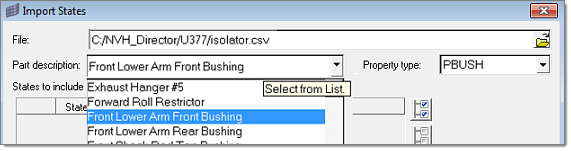
Property states can also be imported using the Import From File option by clicking the ![]() icon to open the Import States dialog.
icon to open the Import States dialog.