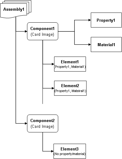
*INITIAL_VELOCITY_(Option)
LS-DYNA keywords used for defining initial velocity.
LS-DYNA keyword
|
Velocity applied to …
|
Setup in HyperMesh
|
*INITIAL_VELOCITY
|
set of nodes, *SET_NODE_LIST
|
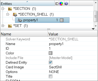
Entity set of nodes, load collector with InitialVel card image
|
*INITIAL_VELOCITY_GENERATION
|
one *PART or set of parts, *SET_PART_LIST
|
Entity set of comps, load collector with InitialVel card image
|
*INITIAL_VELOCITY_NODE
|
individual nodes
|
Created from Velocity panel, organized in load collector with no card image
|
*SET
Graphically view a set’s contents in the Entity Sets panel using the review function.
HyperMesh entity configurations and types
HyperMesh elements and loads have two identifiers:
| • | Configuration - a HyperMesh core feature. |
| • | Type - defined by the loaded FE output template. A configuration can support multiple types. Before creating elements or loads, select the desired type from either the Elem Types panel. |
Only use the Load Types subpanel to directly create loads on nodes or elements. For all other cases, define loads by creating a load collector with a card image. For example, *INITIAL_VELOCITY_NODE (applied directly to nodes) is created from the Velocities panel, while *INITIAL_VELOCITY (applied to nodes in a set) is a load collector with the InitialVel card image.
View a list of element and load configurations in the Elem Types panel and the Load Types panel, respectively.
Elem Types panel
Load Types panel
Some element configurations are rigid and quad4. When you load a dyna.key template, the following types of the rigid configuration are available: RgdBody, ConNode, and GenWeld (*CONSTRAINED_NODAL_RIGID_BODY, *CONSTRAINED_NODE_SET, and *CONSTRAINED_GENERALIZED_WELD_SPOT).
Similarly, some load configurations are force and pressure. Types of the pressure configuration are ShellPres and SegmentPre (*LOAD_SHELL_ELEMENT and *LOAD_SEGMENT).
Most element and load configurations have their own panels. For example, rigids are created with the Rigids panel and constraints are created with the Constraints panel.
*BOUNDARY_SPC_(Option)
LS-DYNA keywords used for defining nodal single point constraints.
LS-DYNA keyword
|
Constraint applied to …
|
Setup in HyperMesh
|
*BOUNDARY_SPC_NODE
|
individual nodes
|
These are constraints created from the Constraints panel and organized into a load collector with no card image.
|
*BOUNDARY_SPC_SET
|
a set of nodes *SET_NODE_LIST
|
This is an entity set of nodes referenced in a load collector’s BoundSpcSet card image.
|
*CONTACT and *SET_SEGMENT
A LS-DYNA contact is a HyperMesh group. Select groups when you want to manipulate a *CONTACT, such as delete, renumber, or display it off.
LS-DYNA contact master and slave types
LS-DYNA has multiple contact master and slave types from which to choose.
*SET_SEGMENT and Contactsurfs panel
Create a *SET_SEGMENT by right-clicking in the Solver browser and selecting Create > *SET > *SET_SEGMENT from the context menu. Additionally, add and remove elements from an existing *SET_SEGMENT and adjust the normal of segments without adjusting the normal of elements with the Contactsurfs panel.
The graphical representation of a contactsurf is pyramids, one pyramid for each segment. The orientation of a pyramid represents the normal orientation of the segment.
By default, the orientation of a pyramid is the same as the normal of the element underneath.
Exercise objective and tasks
The purpose for this exercise is to help you become familiar with defining LS-DYNA boundary conditions, loads and contacts using Engineering Solutions.
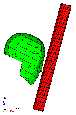
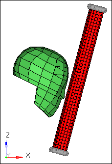
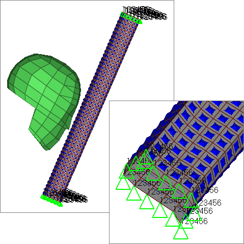
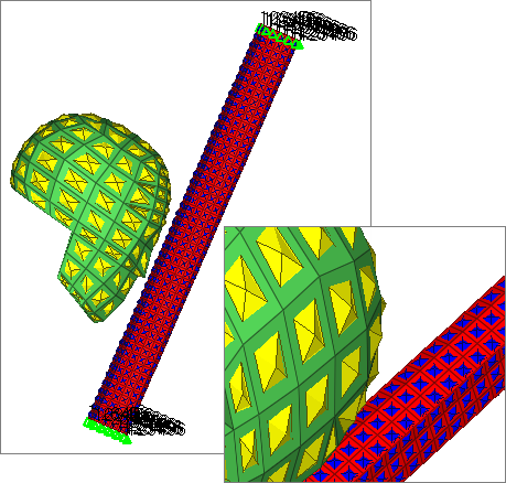
In this exercise you will set up the boundary conditions and load data for a LS-DYNA analysis of a hybrid III dummy head impacting an A-pillar. The head and A-pillar model is depicted below.
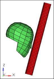
Head and A-pillar model
This exercise contains the following tasks:
| • | Define velocity on all nodes of the head with *INITIAL_VELOCITY |
| • | Constrain the pillar’s end nodes in all six degrees of freedom with *BOUNDARY_SPC_NODE |
| • | Define a contact between the head and A-pillar with *CONTACT_AUTOMATIC_SURFACE_TO_SURFACE |
Step 1: Make sure the Engineering Solutions Crash LS-DYNA user profile is still loaded
| 1. | To select a user profile, click Preferences > User Profiles from the menu bar, or click  on the Standard toolbar. on the Standard toolbar. |
| 2. | Select Engineering Solutions >Crash> LS-DYNA. |
Step 2: Retrieve the model file head_2.hm
| 1. | To open a model file, click File > Open from the menu bar, or click  on the Standard toolbar. on the Standard toolbar. |
| 2. | In the Open Model dialog, open the head_2.hm file. The model appears in the graphics area. |
| 3. | Observe the model using various visual options available in Engineering Solutions (rotation, zooming, and so on). |
Step 3: Create a node set, *SET_NODE_LIST, containing all the nodes in the head component
| 1. | In the Solver browser, right-click and select Create > *SET > *SET_NODE > *SET_NODE_LIST from the context menu. Engineering Solutions creates and opens a new set in the Entity Editor. |
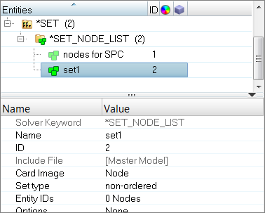
| 2. | For Name, enter Vel_Nodes. |
| 3. | For Entity IDs, click 0 Nodes >> Nodes. |
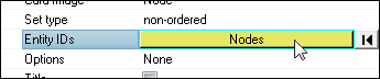
| 4. | In the panel area, click Nodes >> by collector. |
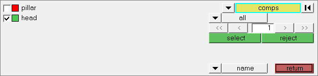
| 5. | Select the component, head. |
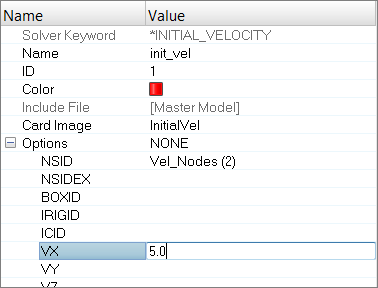
Step 4: Define the velocity
| 1. | In the Solver browser, right-click and select Create > *INITIAL >*INITIAL_VELOCITY from the context menu. Engineering Solutions creates and opens a new load collector in the Entity Editor. |
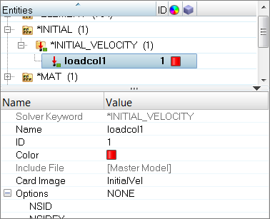
| 2. | For Name, enter init_vel. |
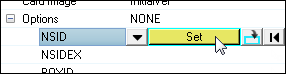
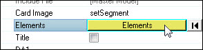
| 3. | Click NSID (Node Set ID), and then click Set. |
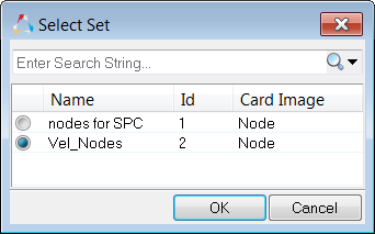
| 4. | In the Select Set dialog, select Vel_Nodes and then click OK. |
| 5. | For VX (x-component of mass center of velocity), enter 5. |
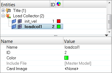
Step 5: Create a load collector for the constraints to be created
| 1. | In the Model browser, right-click and select Create > Load Collector from the context menu. Engineering Solutions creates and opens a new load collector in the Entity Editor. |
| 3. | Optional: Click the Color icon, and select a color to display the load collector. |
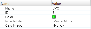
| 4. | Set Card Image to <None>. |
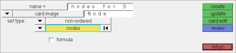
Step 6: Create constraints on the pillar’s end nodes
| 1. | In the Solver browser, right-click and select Create > *BOUNDARY > *BOUNDARY_SPC_NODE from the context menu. The Constraints panel opens. |
| 2. | In the panel area, set the entity selector to nodes. |
| 3. | Click nodes >> by sets. |
| 4. | Select the entity set, nodes for SPC. |
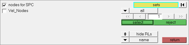
| 5. | Click select. Engineering Solutions selects the nodes at both ends of the pillar. |
| 6. | Verify that all six dof (degree of freedom) checkboxes are selected. |
| 7. | Verify that the load type is set to BoundSPC. |
| 9. | Click return to close the panel. |
Step 7: Define a *SET_SEGMENT for the slave entities, the A-pillar elements
| 1. | In the Solver browser, right-click and select Create > *SET > *SET_SEGMENT > *SET_SEGMENT from the context menu. Engineering Solutions creates and opens a new contactsurf in the Entity Editor. |
| 2. | For Name, enter pillar_slave. |
| 3. | Optional: Click the Color icon, and select a color to display the contactsurf. |
| 4. | For Elements, click 0 Elements >> Elements. |
| 5. | In the panel area, set the second switch to elems. |
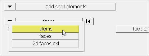
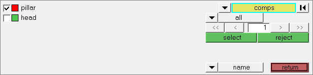
| 6. | Click elems >> by collector. |
| 7. | Select the component, pillar. |
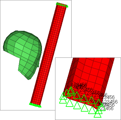
| 10. | Review the contactsurf to make sure that its pyramids are pointing out of the pillar. |
| 11. | Click return to close the panel. |
Step 8: Define a *SET_SEGMENT for the master entities, the head elements
| 1. | In the Solver browser, right-click and select Create > *SET > *SET_SEGMENT > *SET_SEGMENT from the context menu. Engineering Solutions creates and opens a new contactsurf in the Entity Editor. |
| 2. | For Name, enter head_master. |
| 3. | Optional: Click the Color icon, and select a color to display the contactsurf. |
| 4. | For Elements, click 0 Elements >> Elements. |
| 5. | In the panel area, set the first switch to add solid faces. |
| 6. | Set the second switch to elems. |
| 7. | Click elems >> by collector. |
| 8. | Select the component, head. |
| 10. | Using the nodes selector, select three nodes that belong to the same face of a solid element. |
| 11. | In the face angle field, enter 30. |
| 12. | Select the reverse normals checkbox. |
| 14. | Review the contactsurf to make sure that its pyramids are pointing out of the head. |
| 15. | Click return to close the panel. |
Step 9: Create a HyperMesh group with the SurfaceToSurface card image
| 1. | In the Solver browser, right-click and select Create > *CONTACT > *CONTACT_SURFACE_TO_SURFACE > *CONTACT_SURFACE_TO_SURFACE from the context menu. Engineering Solutions creates and opens a new group in the Entity Editor. |
| 2. | For Name, enter contact. |
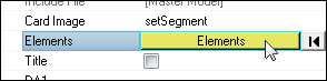
Step 10: Add the slave and master contactsurfs to the HyperMesh group
In this step, the Entity Editor should still be open for the group, contact.
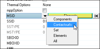
| 1. | In the Entity Editor, click MSID and set the entity selector to contactsurfs. |
| 3. | In the Select Contactsurfs dialog, select head_master and then click OK. |
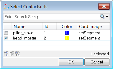
| 4. | Click SSID, and set the entity selector to Contactsurfs. |
| 6. | In the Select Contactsurfs dialog, select pillar_slave and then click OK. |
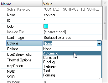
Step 11: Edit the group’s card image to define the AUTOMATIC option
In this step, the Entity Editor should still be open for the group, contact.
| 1. | In the Entity Editor, for the first Options parameter, select Automatic. |
Step 12: Review the group’s master and slave surfaces
| 1. | To open the Interfaces panel, click on the Setup page radio button and then click interfaces. |

| 2. | Go to the add subpanel. |
| 3. | Click name=, and select contact. |
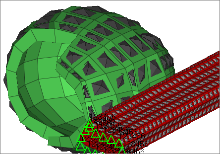
| 4. | Click review. Engineering Solutions temporarily displays the master and slave entities in blue and red, respectively. |
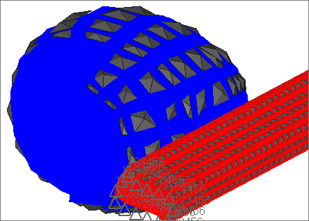
| 5. | Click return to close the panel. |
Step 13 (Optional): Save your work
The exercise is complete. Save your work as a HyperMesh file named head_3.hm.
|