Engineering Solutions

Dimensioning

Dimensioning

Previous topic Next topic Expand/collapse all hidden text  

Dimensioning

Previous topic Next topic JavaScript is required for expanding text JavaScript is required for the print function  

Dimensioning is the act of changing the dimensions of existing geometry, thus changing the basic shape of solids and other enclosed volumes. Dimensioning is accomplished with features, parameters, and dimension manipulators.

Dimension features can be created in the Model browser or Dimensioning panel.

dimensioning_1

Initial dimensions

dimensioning_2

Modified dimensions

hmtoggle_plus1greyDimensioning Concepts

Dimensioning is based on a continuous surface offset functionality. It provides assistance in the selection of the surfaces to offset so that a change to the selected dimension can occur, and calculates the offset values required for each surface to achieve the specified dimension.

The continuous offset modifies both the surfaces you selected for the offset and the adjacent involved surfaces that must also be modified so that the result will remain as continuous as the initial input.

These "selected" and "involved" surfaces are modified with different rules.

Selected surfaces
oOffset by a constant value that is normal, or in some cases almost normal, to the surface at each point.  For example, a standalone surface is offset by the given constant distance exactly normal to itself.

dimensioning_3

Normal offset of a standalone surface.

oWhen the adjacent surfaces form a corner between them, the exact normal offset will result in either disconnected surfaces or in intersecting surfaces (for example if the offset was performed in the opposite direction).

dimensioning_4

Exact normal offset of the adjacent surfaces creates a rupture.

oA continuous result that is consistent with the given offset distance is obtained by reconciling the offset vectors of the vertices shared by the surfaces being offset.

dimensioning_5

Reconciled offset vectors at shared edge.

Involved Surfaces
oThe edges of the involved surfaces that are shared with the selected surfaces move with the selected surfaces.
oThe edges of the involved surfaces that do not have a common point with the selected surfaces do not move (for example they are locked).
oThe offset of the edges that connect both the moving and the locked involved surface edges is defined by interpolation. Different interpolation methods are available.


In general cases, the target dimension between the selected vertices is achieved by offsetting the surfaces that contain the vertices in an infinite number of ways. To avoid this, two rules are implemented.

If both dimension ends (both vertices) are allowed to move, an attempt is made to move them by the same distance whenever possible.
If possible, the dimension ends are moved in such a way that the direction of the dimension will not change.


Offset Examples

The initial positions of the vertices are marked with temp nodes to enable the changes can be easily seen. The locked state of the dimension manipulators is indicated by the lock icons.

Note:These examples are not cumulative, so no two images are directly related. The first image, showing the dimensions of 3, 4, and 5, is the starting point from which all of the other examples derive.

dimensioning_6

Original model; 3 dimensions selected.

dimensioning_6_2

Dim 4 changed to 5; top and bottom move.

dimensioning_7

Dim 4 changed to 5; top moves, bottom locked.    

dimensioning_7_2

Dim 5 (diagonal) changed to 6; all sides move.

dimensioning_8

Dim 5 changed to 6; only top moves.

dimensioning_8_2

Dim 5 changed to 6; only right side moves.


All geometry transformation tools are numerical tools that operate with some accuracy defined by the tolerances, such as the geometry cleanup tolerance set in the Options panel. Curved surfaces and lines have internal structures in 3D that are invisible to the user. Significantly reducing the size of such an entity so that these structures fall below the tolerances may result in a structure simplification that you cannot notice at first; the structural data will be lost.  When this occurs any subsequent increase in the size will not restore the initial structures. For example, reducing a cylinder diameter 100 times and then increasing the diameter 100 times may not lead to the same cylinder; in some cases, a complex internal representation of the cylinder may lead to a corrupt surface. In general, transformation of a curved entity may result in both the simplification or complication of its internal structure. It is therefore not recommended to perform multiple transformations on curved entities.


hmtoggle_plus1greyDimension Manipulators

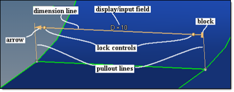
Dimension manipulators are used to alter selected dimensions of solid entities. A dimension manipulator consists of:

Dimension line.  A segment parallel to the line that connects the selected points, but is shifted off the selected points for visibility. The terms manipulator direction and manipulator ends are also used, which are the same as the dimension line direction and the dimension line ends.
Pullout lines.  Two parallel segments that connect the ends of the dimension line with the selected points.
Lock icons.  Arrow (movable) and block (locked) icons indicate the lock state of a manipulator end.
Lock controls.  Sphere handles, located near the lock icons, enable the lock state of a manipulator end to be modified.
Display/input field.  Displays the current dimension value, which can be modified or deleted. This value can be modified or deleted. Deleting the value deletes the the manipulator. For dimensions that are parameterized, an "&" symbol will appear before the dimension. Editing a parameterized dimension directly edits the parameter, or parameter expression.

dimension_manipulators_1

Dimension manipulator objects.


hmtoggle_plus1greyCreating & Modifying Dimensions

Dimensioning is accomplished with features, parameters, and dimension manipulators.

Create a dimension feature in the Model browser or Dimensioning panel.

When you create a dimension feature, you must define two fixed points (vertices) between the opposite surfaces where the dimension is defined. A dimension manipulator is then created between these fixed points (Point1 and Point2).

You must also define a parameterization method. By default, a new parameter is created and assigned to a dimension feature. You can also elect to assign an existing parameter to the new dimension feature, or assign no parameter. A new parameter can be created and assigned to an existing dimension feature via the Create Parameter option in the Entity Editor context menu. A new parameter is given the name provided in the name entry. However, if a parameter with that name already exists, an incremental name is given. The name is also subject to the LS-DYNA 8-character limit for parameter entities.

When changing several dimensions, each dimension change is performed separately using the respective manipulator. However, if multiple dimensions are linked to the same parameter or parameter expression, they will be updated simultaneously.

When dimensions are modified, a very limited check for mutual penetrations of the repositioned surfaces is performed.  It is the your responsibility to ensure that the new dimensions are appropriate.


You can modify dimensions in the Entity Editor, or by clicking the dimension's corresponding label in the graphics area and entering a new value.

The locked end of the dimension manipulator defines the direction in which the affected surfaces move when the dimension is modified. For a dimension to be modified, one or both ends of the dimension manipulator must unlocked.

When dimensions cannot be modified, the locked side is set to Both and you may use the Sides Selection advanced option to specify how the dimension should be changed, when possible.

dimension_manipulators_2


hmtoggle_plus1greyDimension Feature Control Options

In the Entity Editor, additional options can be defined for dimension features.

Automatic

A heuristic algorithm is used to try and decide which of the two interpolation methods to apply for each individual, applicable involved surface.

Local

A Local Coordinate System (LSC) 2D interpolation method that "slides" along the surfaces to determine the offset vectors, which are then interpolated and combined into the interpolated offset at each point. Selected surfaces are always interpolated using this method.

Global

A global coordinate system 1D linear interpolation method that stretches/compresses a surface proportionally in a global 1D. Only applicable when all of the offset vectors at the surface's vertices are collinear and proportional to the distance parameter along their common direction.

dimensioning_options_5

Interpolation of the same offset vectors at the vertices for both methods.


When a selected surface is offset, the involved surfaces must be modified to keep the continuity of the model.

Surfaces can be modified by dragging the involved surface behind the selected surface, or by defining it as a "slider" along which the selected surface slides.

The Minimum Slide angle determines which method is used. If the slide angle is more than the specified value, then the involved surface will slide; otherwise it will drag.

When the involved surface is a slider, the orientation of the surface does not change for planar surfaces. However, for curved involved surfaces, the sliding directions are defined by the tangents to the surface where it is adjacent to the selected surface. Sliding of the selected and involved surfaces along these directions may also result in some change to the shape of the involved surface.

dimensioning_options_6

Original model

dimensioning_options_7

Involved surface dragged

Involved surface as slider

Dimension modified to D=0.4.


When enabled, the portions of the offset surfaces that fold into themselves or adjacent surfaces (portions of surfaces that penetrate themselves or adjacent surfaces along the edges they are adjacent over) are removed.

For example, suppose that the slide angle is greater than the Minimum Slide Angle and the value in the dimension manipulator is set to 1. If this option is off, the involved surface will slide and ignore the self-penetration, resulting in a corrupt model. If this option is enabled, the involved surface will slide as far as possible without causing self-penetration. This may not allow the specified dimension to be reached, but will not result in a corrupt model.

dimensioning_options_8a

dimensioning_options_8b

Remove collapse surfaces off

Remove collapse surfaces on

Dimension modified to D=1.

Another useful application is for the removal of holes. If the hole diameter is set to 0 and this option is on, the hole will be removed. If the option is off, a small "straw surface" will still remain.

In general, unless it is known that collapsed surfaces will result, it is better to keep this option off for performance reasons, as this option has no effect on general cases that do not result in penetration.


Auto

The surfaces to offset are automatically selected using the following rules:

1.Surfaces adjacent to the manipulator ends are selected if the angle between the normal to the surface at the dimension end and the dimension direction is less than the Max Pick Tilt.

If surfaces are selected at both ends for the specified Max Pick Tilt value, then the lock control handles will allow for the manual manipulation of the offset scenario.

dimensioning_options_1

Angle between the normal to the surface and the manipulator direction.

2.Surfaces adjacent to the selected surfaces are appended, provided that they are planar and the angle along the edge over which they are adjacent to the already selected surface is less than the Max Expand Angle.
3.The total area of the selected surfaces at each end is calculated. If the area of the selected surfaces at one end is more than the Side Selection Area Ratio and larger than the area of the selected surfaces at the other end, then the surfaces on the larger area side are unselected. In this case, only the surfaces at the smaller area side are used to offset.

dimensioning_options_2

side selection area ratio = 3

side selection area ratio = 1.5

Bottom surface area twice as much as the top surface, so bottom will not move (note the lock indicator).

The ends of the dimension lines that are allowed to move are marked with arrows, while the locked ends are marked with blocks.

dimensioning_options_3

Examples of lock icons

When both sides have surfaces that satisfy rule 1 above, rule 3 can be manually overridden. In this case the lock controls (spheres near the icons) define the offset scenario. Clicking the lock control handles will toggle the lock state between locked and unlocked for that end. If a lock control state is manually specified, then rule 3 is ignored for that dimension manipulator and the Side Selection Area Ratio option no longer applies.

When Sides Selection is set to Manual, the surfaces to offset are selected using the Surfaces to Move selector.  The manual surface selection is then governed by the lock state of the dimension manipulator ends.

Note:Out of the selected surfaces, only those that are linked to at least one of the dimension manipulator ends by a continuous selection are actually used in the offset.

With the manual selection, the use of Separator Lines is also available (see the surface edit subpanel for details).


Manual

Manually select the surfaces to offset.

In the images below, the three highlighted surfaces are selected in order to change the dimension from 50.5 to 70 and move the wall to a new position.

dimensioning_options_4

Dim 50.5 changed to 70 to move the wall.

With manual side selection, surfaces are selected erroneously, and the results can be unexpected or catastrophic.


hmtoggle_plus1greyAdvanced Considerations

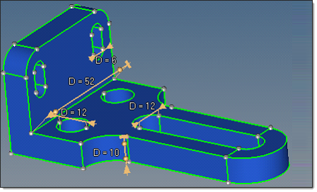
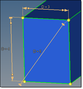
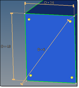
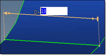
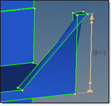
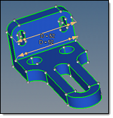
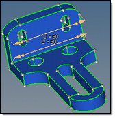
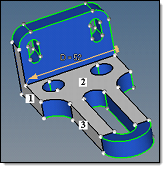
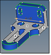
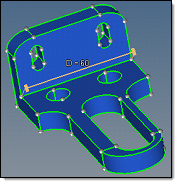
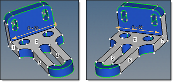
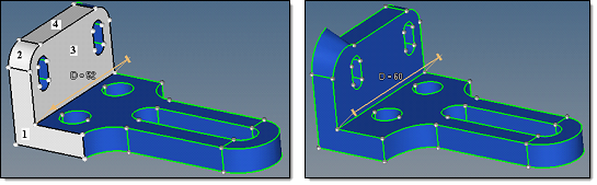
In practice, changing of a linear dimension in a model normally implies either stretching/compressing in the direction of the modified dimension or changing of a diameter/radius. With the dimensioning tool, a combination of both modification types is provided.

In the example below, one of the two D=52 dimensions is changed to D=60. How the offset is performed will give different results (both of which may be valid) depending on which of the two dimension manipulators is changed.

dimensioning_advaced_1a

dimensioning_advaced_1b

dimensioning_advaced_1c

Original model

Edge fillet surfaces selected; fillet radius is scaled

Edge fillet surfaces involved; linear scaling only, fillet curvature changes.

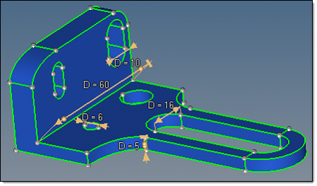
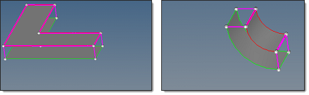
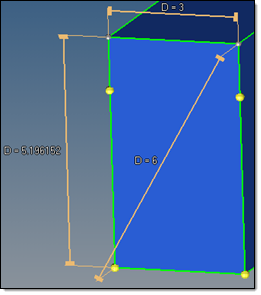
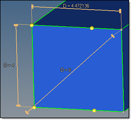
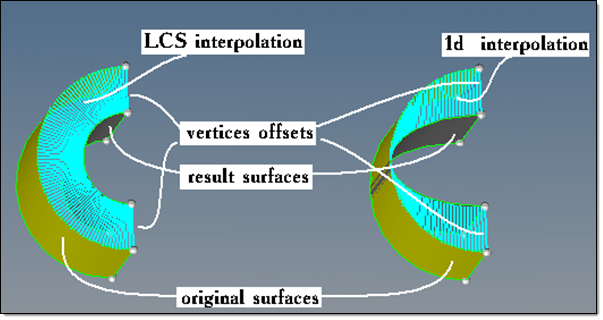
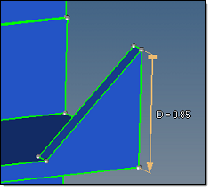
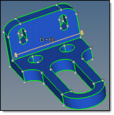
When the value of the upper dimension manipulator is modified from 52 to 60, the edge fillet surfaces are adjacent to the modified manipulator and are offset as selected surfaces. As such, they are offset with the LSC interpolation, which results in a preservation of their shape along with the change in radii.

When the value of the lower dimension manipulator is modified from 52 to 60, the edge fillet surfaces are not adjacent to the modified dimension manipulator and are curved, so they are offset as involved surfaces. Using automatic interpolation, it is recognized that these two curved surfaces can be simply stretched to provide the model continuity via the global interpolation method.

When using manual surface selection and changing the same lower dimension, a variety of results are obtainable depending on the selected surfaces.  Some of the possible results as shown below.

Note:In each row of the 3 images, the first two show the initial selection from two angles (to reveal all of the selected surfaces), while the third shows the results of the dimension change based on those selected surfaces.

dimensioning_advaced_3a

dimensioning_advaced_3b

dimensioning_advaced_3c

Original model, 3 surfaces selected

Original model, 3 surfaces selected

Result of the dimension 52 change  to 60

dimensioning_advaced_4a

dimensioning_advaced_4b

dimensioning_advaced_4c

Original model, 4 surfaces selected

Original model, 4 surfaces selected

Result of the dimension 52 change  to 60

dimensioning_advaced_5a

dimensioning_advaced_5b

dimensioning_advaced_5c

Original model, 5 surfaces selected

Original model, 5 surfaces selected

Result of the dimension 52 change  to 60

dimensioning_advaced_6a

dimensioning_advaced_6b

dimensioning_advaced_6c

Original model, 6 surfaces selected

Original model, 6 surfaces selected

Result of the dimension 52 change  to 60

dimensioning_advaced_7a

dimensioning_advaced_7b

dimensioning_advaced_7c

Original model, 7 surfaces selected

Original model, 7 surfaces selected

Result of the dimension 52 change  to 60

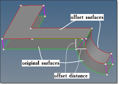
The following steps are used to calculate the offset values of the selected surfaces.

1.The required shift in the dimension manipulator direction is calculated as a difference between the requested distance and the actual distance between the dimension manipulator ends.
2.If both dimension manipulators ends are allowed to move, the required shift is divided by two.

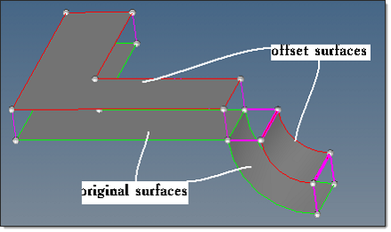
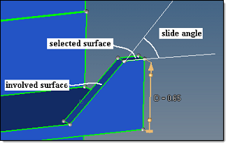
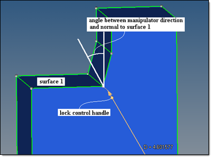
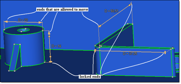
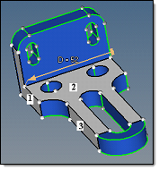
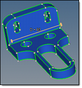
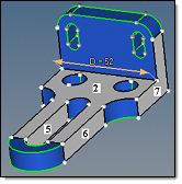
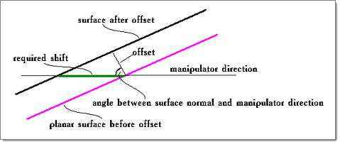
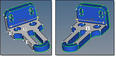
When Sides Selection is set to Auto, an end is allowed to move if it belongs to a surface that is automatically selected to move. When this can be overridden manually by you, the lock controls appear.

When Sides Selection is set to Manual, an end is allowed to move if it belongs to a manually selected surface, and the surface normal at the dimension manipulator end forms an angle with the dimension manipulator direction that is less than arccos(0.05) (87.134016 degrees).

For example, the right end of the dimension manipulator belongs to only the selected surface 2. The normal to surface 2 at the right end creates a 90-degree angle with the dimension manipulator and thus the end is not allowed to move. The left dimension manipulator end belongs to both selected surfaces 1 and 2.  The normal to surface 1 at the left end makes a 0-degree angle with the dimension manipulator direction, and thus the left end is allowed to move.

dimensioning_advaced_8

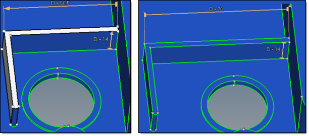
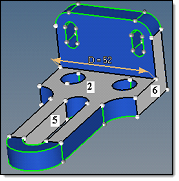
In the following example, the right end belongs to selected surfaces 2 and 7, with the left end belonging to selected surfaces 1 and 2.  Thus, both ends are allowed to move.

dimensioning_advaced_9

3.When only planar surfaces are selected, the absolute value of its normal offset is defined as the absolute value of the required shift multiplied by the cosine between the normal to the surface and the dimension manipulator direction.

dimensioning_advaced_10

For a planar surface, this provides that its shift in the dimension manipulator direction is equal to the required shift.

When curved surfaces are included and the Sides Selection is set to Manual, the rules of the offset value calculations are more complex. The problem in this case originates from the fact that a selected curved surface can provide a smooth link between the selected planar surfaces that are tilted by different angles versus the dimension manipulator direction. When smooth, adjacent surfaces are offset, they must be offset by the same value to ensure continuity of the result, because in this case it is not possible to reconcile the different offset values as discussed earlier. This means that the planar surfaces with a different tilt towards the dimension manipulator direction cannot be offset by different distances, as shown above, when the planar surfaces are smoothly linked by a selected surface.

The current algorithm to define the offset value in the general case (for both curved and planar surfaces) is as follows. For a selected surface adjacent to the dimension manipulator end, its offset is calculated as shown in the image above, based on the normal to the surface at the dimension manipulator end. For a selected surface that is not adjacent to the dimension manipulator end, a chain of selected surfaces that links it to the related end is detected, and the offset is calculated along the chain, from the previous surface to the next. The calculation along the chain is based on the following:

If the surfaces are smoothly adjacent, the offset value is directly passed from one surface to the next.
If the surfaces are not smoothly adjacent, the offset is calculated in such a way that for a planar surface the result as shown in the image above is obtained.

The problem here is that when several chains of selected surfaces connect a selected surface with the related dimension manipulator end, the offset results for the surface obtained along the different chains can contradict each other. Then the dimensioning result may be corrupt. Therefore, it is important to make appropriate manual surface selections.

dimensioning_advaced_11

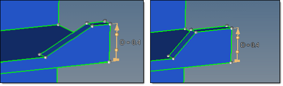
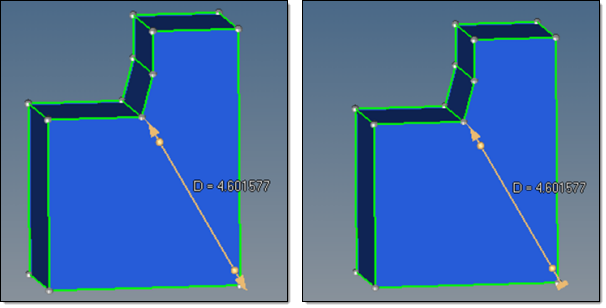
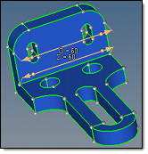
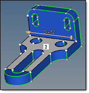
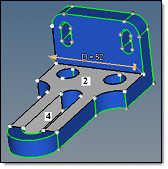
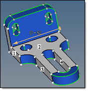
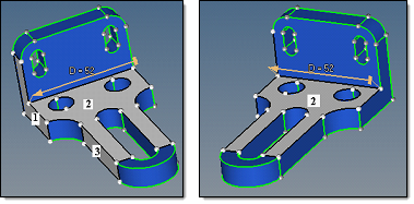
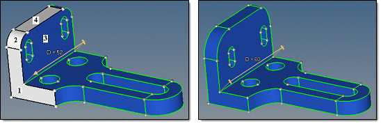
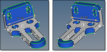
Surfaces 1, 2, and 4 selected, D=52 changed to D=60. Surfaces 1, 2, and 4 offset by 8.

dimensioning_advaced_12

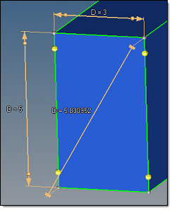
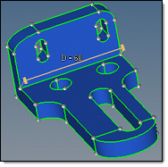
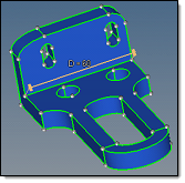
Surfaces 1, 3, and 4 selected, D=52 changed to D=60. Surface 1 offset by 8, Surfaces 3 and 4 by 0.

dimensioning_advaced_13

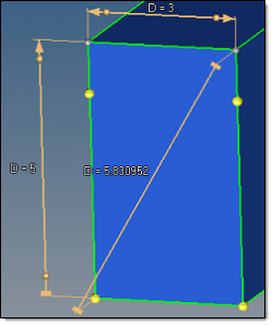
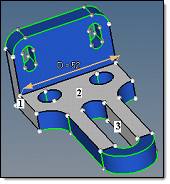
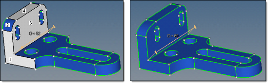
Surfaces 1, 2, 3, and 4 selected, D=52 changed to D=60. The result is corrupt.

4.For each selected surface the sign of the offset is defined so that it will move in the same direction as the dimension manipulator end to which it is related.

A surface can be related to one, and only one, of the dimension manipulator ends. For this, first, the dimension manipulator end must be allowed to move.  Second, the surface should be linked to the dimension manipulator end over a chain of adjacent selected surfaces. Third, in the case when the surface is linked to both dimension manipulator ends which are allowed to move, the surface will be related to the end that is closer to it.

As an example, selected surface 2 will have an offset of 0, because cos(90) = 0.  The purpose for selection of this surface is just to provide a link from the dimension manipulator ends to the other selected surfaces. Surface 1 is at the moving dimension manipulator end, and surface 3 moves as surface 1.

dimensioning_advaced_14

Following the same rules, surfaces 1 and 7 are at the moving dimension manipulator ends. Surfaces 3 and 5 move as surface 1, and surfaces 4 and 6 move as surface 7.

dimensioning_advaced_15


See Also:

Dimensioning Panel

Features

Parameters