Open this dialog via the green Auto button on the BL parameters subpanel when you select Smooth BL from the toggle in the bottom-left corner of the panel.
This utility identifies narrow regions in the model and scales the total boundary layer thickness according to your input.
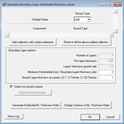
If you already selected components on the Boundary selection subpanel, those components display automatically in this utility with the appropriate Bound Type. Otherwise, you can click the Add collectors with surface elements button and then pick the desired parts of the model. When selecting components this way, you will need to also specify the Bound Type for each component. Each component also has a Remove button to remove it from the list (the component itself is not deleted from the model, only removed from this dialog). Finally, you can clear all components by clicking the Remove all the above added collectors button.
The Number of Layers, First layer thickness, and Layers’ thickness growth rate are automatically populated with the values from the CFD Tetramesh panel.
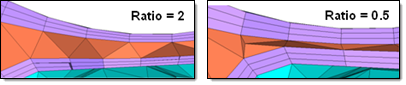
The Minimum (Tetrahedral-Core/Boundary Layer) thickness ratio value is the minimum ratio between the thickness of the tetrahedral core and the boundary layer. This value must be more than zero, but decimal values are accepted. The higher this value, the more the boundary layer elements will be compressed to keep the core open.
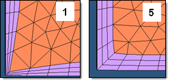
The Bound Layer thickness at corners adjusts the total thickness of boundary layers in corners to avoid elements getting distorted or interfering with other boundary layer elements because of the default hyperbolic growth of the boundary layer. The smaller this value is, the smaller the thickness of the boundary layer at corners will be relative to the nominal total boundary layer thickness. The image below shows the effects on the same model using values of 1 and 5.
The Check for closed volume checkbox causes the utility to run a check to make sure that the selected elements form enclosed volumes without any holes. Enclosed volumes simplify meshing because the direction of boundary layer growth is always inward. However, in some cases where a volume is not enclosed, the mesher creates boundary layers based on the elements' normal direction.
If the normal faces the wrong way, the boundary layers might accidentally extend in the wrong direction; when this occurs, you can uncheck this option, and then click the Adjust Element Normals button to switch the normals of the elements that generated boundary layers in the wrong direction.
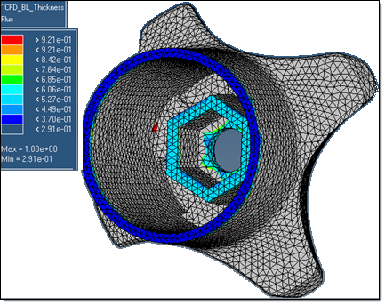
Finally the Generate Distributed BL Thickness Ratio button creates the distributed boundary layers, placing their thickness values in the load collector ^CFD_BL_Thickness.
If you wish to display contours of the Boundary Layers' Thickness Ratio, click the Display Contours of BL Thickness Ratio button.
When finished generating the distributed boundary layers, click Close to close the dialog and return to the BL parameters subpanel.
See Also:
CFD Tetramesh Panel
Dynamic BL thickness reduction


