|
»Click here to display Table of Contents«
|

Edit Module |

|

|

|

|
|
Edit Module |
|
|

|

|
|
»Click here to display Table of Contents«
|
Edit Module |
|
|
|
|
|
Edit Module |
|
|
|
|
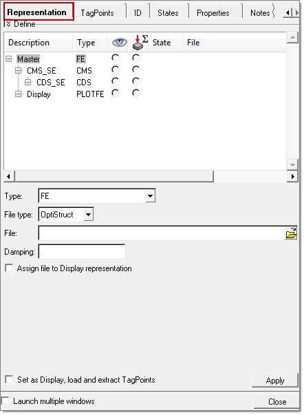
To manage any of the modules shown in the Assembly browser, right-click on a module and select Edit Representations. This opens the Edit Module tab, and the Representation sub-tab is shown.
A module representation is simply a way a module can be represented. Valid representation types can be assigned using the Type drop-down menu and include:
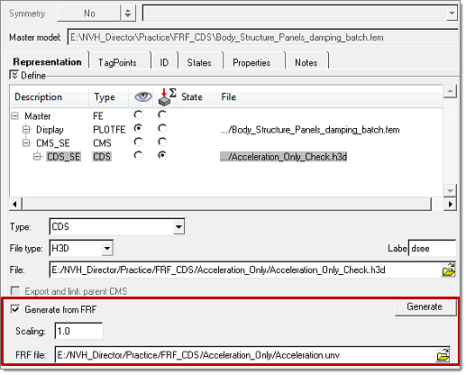
Right-clicking the white space will give you the options to add, remove, or edit the description of the selected representation. A file assigned to the root representation can be optionally auto-assigned to be a Display representation (PLOTFE type) simultaneously by checking the Assign file to Display representation checkbox. A representation can be auto-selected to be the Display representation by checking the Set as Display, load and extract TagPoints checkbox. This will be followed by the file being imported into the 3D graphics window and TagPoints defined in the file extracted. Once all representations are defined, click the Assembly Browser tab to review the assembly hierarchy with active Display and Analysis representations. Define Test FRFs (UNV) as module representationsAn additional option in CDS-SE allows you to read UNV files that have test FRF information and convert them into a CDS-H3D file. This can then be assigned as module representation.
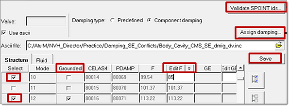
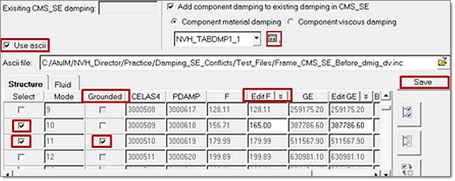
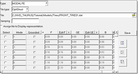
Modal model review and parameter modificationsThese features allow for the review of modal model parameters of reduced model representations (both CMS-SE and Modal-FE) and modifying them. This will help you in understanding the effect of changing these parameters on NVH responses, without generating reduced models with necessary modifications. The related list of features for CMS-SE are:
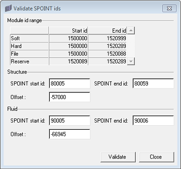
Clicking Validate SPOINT ids opens this dialog
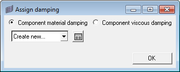
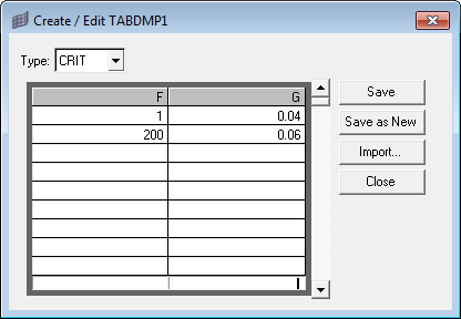
Clicking Assign damping opens this dialog
Clicking the For Modal-FE, modal parameters are populated on loading the representation file. The options for review and modifications of parameters are the same as for CMS-SE.
|
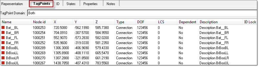
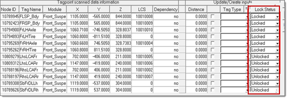
A Tagpoint is a special point used in the assembly for connection, input, response and plot purposes. It consists of a grid with a set of relevant properties, such as name, description and dependency.
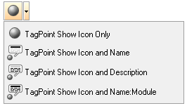
Tagpoints are displayed in the 3D graphics area and can be customized via the NVH Module Display toolbar. By default, tagpoints are indicated with a gray sphere along with the label. Other options are available using the pull-down menu.
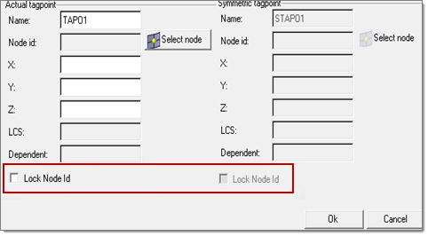
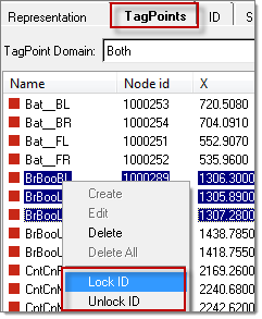
To add a tagpoint, right-click inside the tagpoint list in the Tagpoint tab and select Extract All to extract TagPoints from the comments added to the 10th field of the grids in the loaded Display model. Lock ID
|
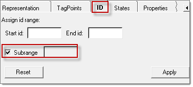
Sub rangingSub ranging provides you with a means to reserve a range so that it is not occupied and not referred by anybody. This is primarily needed if you want to reserve a certain ID range for a specific use and should not be occupied by other entities. Some customers follow a convention of reserving the first 10,000 ID’s of nodes for connections for every include. They would like to reserve them at the start and then allocate these ID’s to the tagpoints pertaining to respective includes, by releasing the reserve range, when it is required.
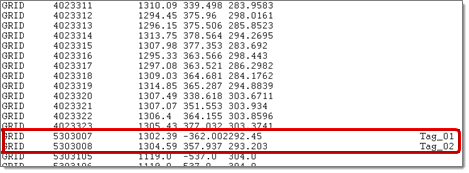
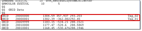
The following images show a sample file with and without sub ranging.
Front stab bar without sub ranging
Front stab bar with sub ranging |