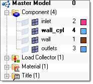
| • | To export a mesh for FLUENT, display all the components/collectors with surface elements (for boundary condition zones) and volume elements, such as fluids and possibly solids. All other components in your database should not be visible/displayed. |
| • | Place all volume elements associated with the same fluid domain on a single collector. The same applies if the model contains solid parts. |
| • | Use the following naming convention for collectors: fluid* for fluid collectors (for example fluid1, fluidAir), solid* for solid collectors and wall*, inflow*, outflow*, symm*, and so on for boundary collectors. Following these guidelines will ensure that FLUENT does not rename or split collectors unnecessarily. |
| • | If the component name starts with "Interior-<Comp name>" it is considered as "Interior." If the name of the component starts with "Interface-<Comp name>" it is considered as "Interface." |
| • | If the component between two volumes is defined as "Interface", it will split the domain in FLUENT. |
| • | When simulating conjugate heat transfer, it is necessary to include a collector with interface elements between solids and fluids, for example wall_AB, containing 2D elements generated from ^faces from either the solid or the fluid collector that are in contact. When FLUENT reads this group of elements, FLUENT finds that this group is shared by solid elements on one side and fluid elements on the other and will automatically generate the corresponding "*-shadow" group used in conjugate heat transfer simulations. If you do not create this collector, HyperMesh will create such a component automatically when exporting the .cas file. |
| • | For consistency, use the organize/move command to create collectors with boundary zones from the ^faces collector. |
| • | Use the .cas/.msh format to export meshes for any version of FLUENT-3d. Using this option all of your component names are used by FLUENT, as shown below: |


Additionally, using the .cas format allows you to reuse FLUENT *.cas simulation settings and associated boundary conditions: you can load/import a FLUENT .cas model and after making geometry/mesh changes, you can create/save a new .cas simulation model reusing simulation settings and boundary conditions from the original .cas file that was read in. This is done when the new .cas file is saved, after you have made modifications to the original/imported .cas model. While saving you will be prompted for the name of the “original” .cas file. This file is read by Engineering Solutions and all simulation settings and boundary conditions are reused when saving the new/modified .cas file. All boundary that existed in the original .cas file and that have not been renamed will be set with the same boundary condition type and parameters as in the original .cas file.
| • | To export a 2d mesh for FLUENT-2d, make sure that the mesh has been created in the global X-Y plane (with a constant value of Z for all nodes). |
The 2d mesh boundary (free edges) is used to specify boundary zones in FLUENT. Use the ^edges command to find all the free edges and then use the Organize panel to move groups of edge elements to components named according to the boundary condition; for example: inlet1, inlet2, outlet, wall, sym, and so on.
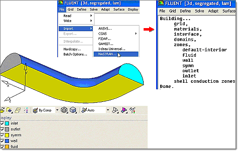
| • | If you want to use the Nastran format to export meshes for FLUENT-3d, NOTE: it is better to use the .cas/.msh format for FLUENT-3d release 6.3.* which is not as good as release 6.2.* for importing Nastran files. You can import a mesh in Nastran format into FLUENT as follows: click File > Import > Nastran and select the .nas file exported by the Fluent: Mesh command. |

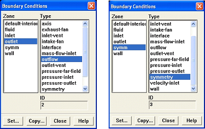
| • | If you use collector names following the naming guidelines given above, all boundary condition zones have the correct default type as shown in the following image taken from FLUENT’s Boundary Conditions window: |

| • | Before exporting meshes for FLUENT, ensure that fluid elements that belong to a single fluid domain are not split among several fluid collectors, otherwise FLUENT will split boundary zones shared by two or more fluid collectors into as many boundary zones as fluid zones/collectors are in contact with each boundary zone and this may not be desirable. The same applies to solid components. |
See Also:
Tips for CFD Solvers


