HyperWorks Release Notes

FEKO

FEKO

Previous topic Next topic Expand/collapse all hidden text  

FEKO

Previous topic Next topic JavaScript is required for expanding text JavaScript is required for the print function  

Altair® FEKO® is a comprehensive computational electromagnetics (CEM) software used widely in the telecommunications, automobile, aerospace and defence industries.

FEKO offers several frequency and time domain electromagnetic (EM) solvers under a single license. Hybridisation of these methods enables the efficient solution of a broad spectrum of EM problems including analyses of antennas, microstrip circuits, RF components and biomedical systems, placement of antennas on electrically large structures, calculating scattering effects and performing electromagnetic compatibility (EMC) studies.


Highlights


The FEKO 2017 release is packed with features and improvements to create a platform for simulation-driven innovation. Since the 14.0 release, features have been made available to users in quarterly updates allowing users to take advantage of the extended capabilities as soon as they are ready. The most notable extensions in this release are:

hmtoggle_arrow1Computational Performance Improvements
The finite difference time domain (FDTD) solver supports OpenMP and MPI parallelisation allowing users to take full advantage of machines with multiple cores and multiple computation nodes in cluster environments.

feko_2017_01

The ray launching geometrical optics (RL-GO) solver has been improved considerably in terms of speed and resource efficiency (memory reduction). Innovative algorithms select the most suitable ray distribution and automatically determine when enough ray interactions have been taken into account.

feko_2017_02


hmtoggle_arrow1Extensions to the EM Solver Expands the Portfolio of Physics that can be Solved
3D anisotropic materials can be modelled using the FEM and FDTD solvers. 3D anisotropic media make it possible to solve circulators and other interesting devices.

feko_2017_03

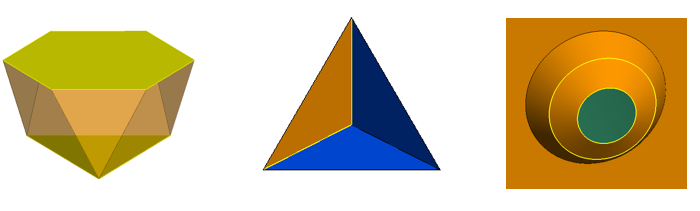
Modelling of 3D anisotropic materials:
The power density of a 3-port Y-junction circulator with a ferrite post in the centre.

Improved multilevel fast multipole method (MLFMM) stabilisation allows large problems with intricate detail, that traditionally could have prevented the MLFMM to converge, to be solved.

feko_2017_04

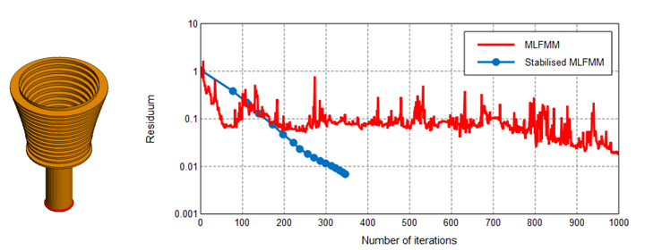
Improved stabilisation of the MLFMM solver addresses models with severe convergence problems such as the corrugated
horn antenna shown above. The graph shows the typical reduction in the required number of iterations to reach convergence.

hmtoggle_arrow1Improved Model Creation and Mesh Preparation
Extensions to the loft operator make the creation of transitions fast and easy. The new loft extensions also provide the user with more control over the loft surface creation.

feko_2017_05

Extensions to the loft operator enable the lofting of different faces to create solids, lofting edges within parts and lofting circular shapes.

A new mesh engine generates improved meshes that often consist of fewer mesh elements that directly relate to a reduction of resources and faster simulation.

feko_2017_06

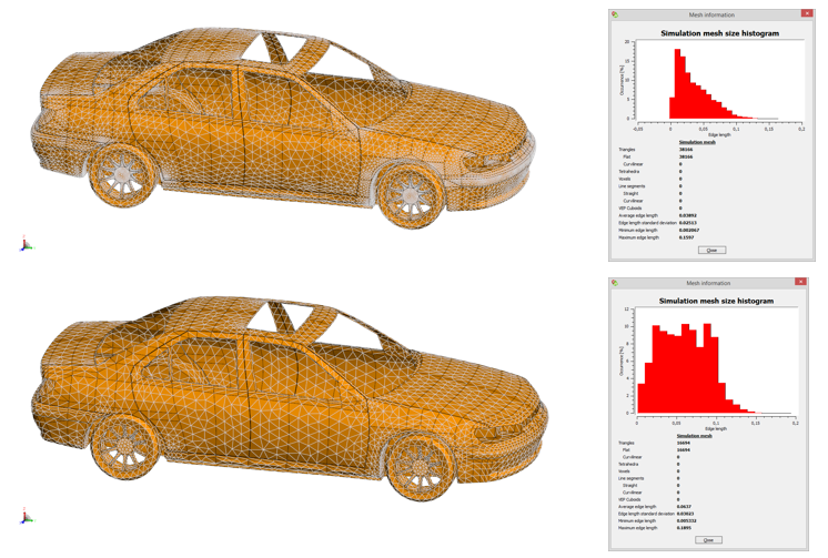
A new mesh engine is introduced that will replace the existing mesh engine in future releases:
Top: Mesh of a car generated by the legacy mesh engine and the mesh histogram.
Bottom: Mesh of a car generated by the new mesh engine and the mesh histogram.

hmtoggle_arrow1Model Interrogation, Validation and Reporting Improvements Make Simulation-Driven Innovation Easy
The Cartesian surface graph allows users to visualise more data on a single graph, making it easier to identify patterns and make design decisions for further simulation. (14.0.430)

feko_2017_07

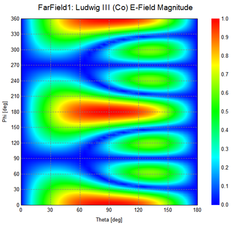
An example of a Cartesian surface graph, a flat colour plot with results plotted against two independent axes.

Improvements to the windscreen visualisation allow users to see the layers and their relationship with regards to the active elements. This ensures correct model setup.feko_2017_08

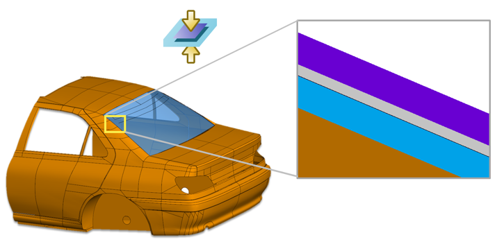
Windscreen layer visualisation

Graphs have been extended with options to add text and shapes that allow improved reporting from within the FEKO interface.

feko_2017_09

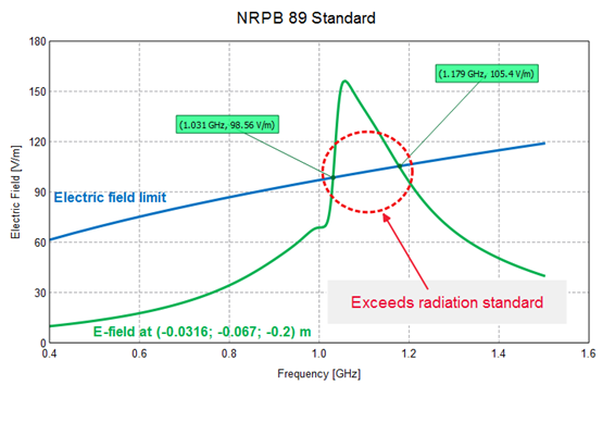
Text and shapes on a 2D graph. In this example, the graph is annotated to indicate where the electric field exceeds the maximum limit for the NRPB 89 standard.


The items mentioned above are only a few of the highlights of the last year’s development and the sections that follow provide a more detailed list of the changes. In addition to the FEKO 2017 Release Notes, this document also contains a list of all features released as updates to FEKO 14.0. The version in which a particular feature was released can be determined from the corresponding version number in parentheses.