|
»Click here to display Table of Contents«
|

HyperMesh |

|

|

|

|
|
HyperMesh |
|
|

|

|
|
»Click here to display Table of Contents«
|
HyperMesh |
|
|
|
|
|
HyperMesh |
|
|
|
|
General
|
|
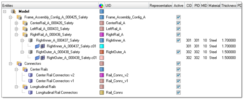
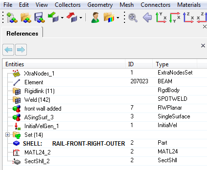
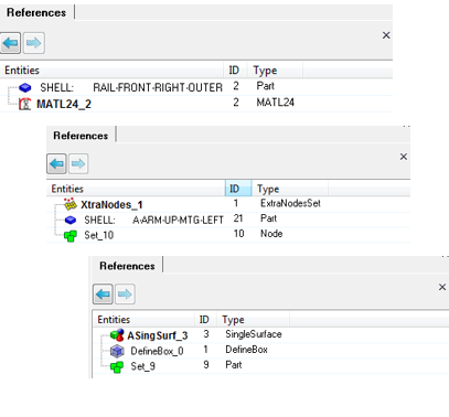
Improvements have been made to the usability of the XRef tool. It’s now easier to traverse through the references and cross-referenced entities.
|
Within the browser, new options have been added so that it’s possible to delete an entity and its referenced entities. In addition, and as per the Delete panel, it’s now possible to delete empty and unused data directly from the browser.
|
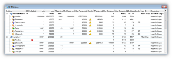
A new history mechanism is enabled which allows, by default, one hundred undo/redo operations. The undo/redo support is focused on entity creation and editing, most geometry and meshing operations plus more. Not all operations are supported and if one of those operations is executed then the history mechanism is reset.
|
For LS-DYNA, it’s possible to view the data as per the Include structure.
|
In addition to Ls-Dyna, Box Trim is now enabled for OptiStruct, Nastran and Abaqus solver profiles.
|
A new selection mode is enabled for the selection of faces and edges. Pressure and Contact creation are the two main areas where the selection modes are available.
|
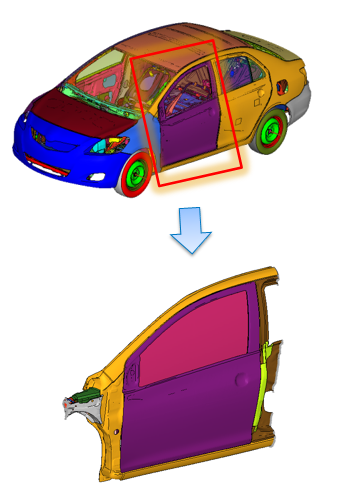
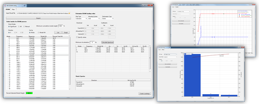
Dynamic Design Analysis Method is used to simulate underwater explosions. Within HyperMesh, there is a new tool to support the setup of response spectrum analysis. It is available for the Abaqus solver profile.
|
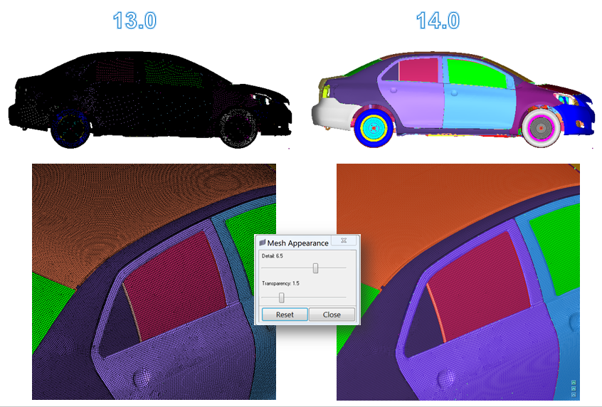
Significant performance and usability improvements have been achieved by automatically controlling the amount of mesh line detail displayed. The mesh lines are drawn appropriately dependent on the zoom level of the model. For example, if the model is viewed at a global level, the mesh lines will be suppressed, when the model is viewed more closely, then mesh lines will appear. Improvements have also been made to the visualization and performance of the drawing of boundary conditions, node selection, transparency and utilizing current GPU technology to increase large model handling. A new “optimize view controls” option helps increase dynamic model handling speeds by simplifying graphics.
|
Updated support for 3Dconnexion devices, including better default settings and usability controls through the updated driver APIs within HyperMesh.
|
HyperMesh will now try to utilize the dedicated GPU (graphics) in a laptop or notebook using combination of Intel’s integrated GPU and NVIDIA’s or AMD’s dedicated graphics cards.
|
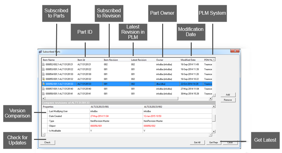
It’s now possible to subscribe to a part(s) in PDM, and if a change occurs the user, within HyperMesh, can be notified of those changes so that they can download and import the amended CAD file.
|
H3D files exported from HyperMesh can now optionally contain contour results plotted from the Post panel, the Comparison tool, and the Check Elems panel.
|
|
Connectors
The CEE can be found in the lower part of the Connector browser and gives easy access to all important connector attributes of currently selected connectors. With the CEE it’s now possible to precisely change single attributes and realize various connectors at once. All attributes are described with tooltips.
|
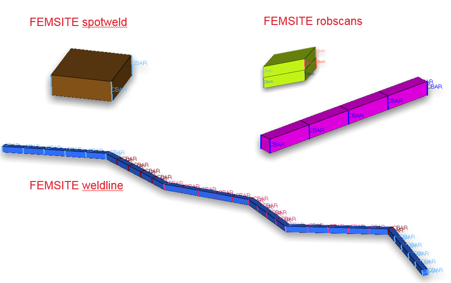
A new interface is enabled to support the FEMSITE Connector capabilities.
|
The connector color is changed from green (realized) to blue (modified) now, if their attributes have been changed in the Connector Entity Editor. This signifies that the information on the connector might be inconsistent with the current realization state. A following re-realization turns the connector to green or red and the state is then re-sync’d. A new function is added which will re-realize all “modified” connectors with their updated attributes.
|
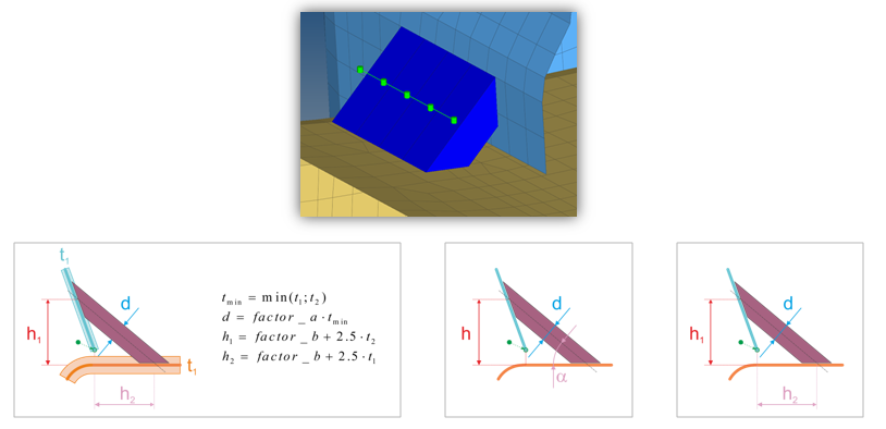
Hexa and penta seam realizations are slightly differently created dependent on the weld type (B, L, T). Before the realization is performed the angle between the two parts is measured. Dependent on that angle a lap-, t-or butt-weld is performed. The connector angle control is located in the general connector options The general penta seam realization type has been re-introduced.
|
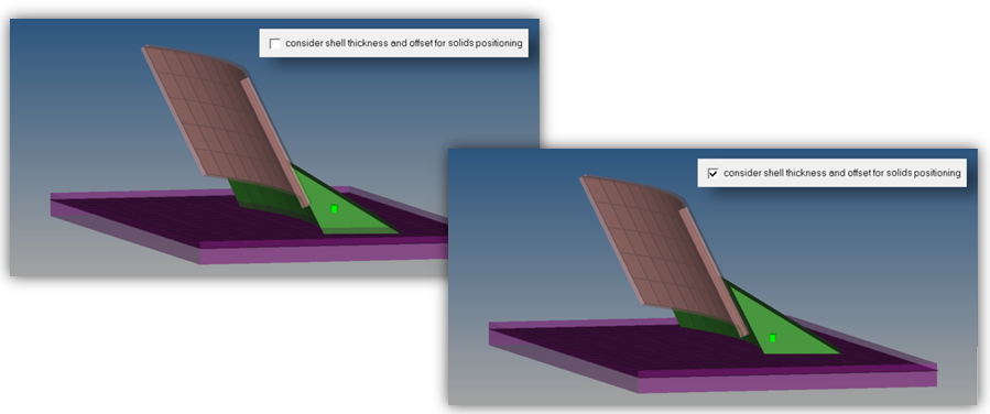
The connector option “consider shell thickness and offset for solid positioning” is now supported for penta seams.
|
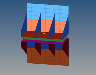
The hexa adhesive seam realization now has options like shell gap, constant thickness, mid thickness for T-cases. The hexa height is dependent on these settings.
|
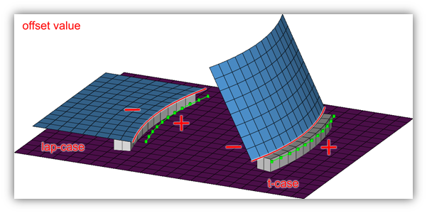
For the hexa adhesive seam realization the position of the hexas related to the free edge can be user defined. The negative side is defined as the side of the smaller angle measured at the free edge between the two parts to be connected.
|
A new seam realization type “hexa (tapered T)” has been implemented for various solvers. This realization type is intended to be used for t-cases. The size and exact position can be defined thickness dependent or the exact dimension and position parameters can be given.
|
Spot connectors can be converted to bolt connectors and vice versa. This can be done from the context menu in the lower part of the Connector browser.
|
A new entity type part has been introduced into HyperMesh. This entity type is also being supported for being used as link for the connector technology.
|
For connectors different link types are supported. It’s possible now to convert certain link types into another link type. Conversion is supported between part-, component- and property-links.
|
These realization types can be performed without the creation of the cap elements. Then the cap angle as well as the runoff angle are not considered anymore.
|
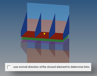
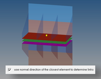
This option can be found in the Spot Connector options. In certain situations, when many small element cluster of different link candidates are very close to the connector position it might happen, that unintended links are found. To prevent this behavior the option can be activated and the normal direction of the closest link is considered for further link detection.
|
For seam imprint the imprint size can now be defined with a certain value, the average mesh size or as the pitch size.
|
For the RBE3 (load transfer) realization the tolerance is used to detect the nodes, which should be considered for the connection. To be able to limit the number of attached node a limit per layer can be defined.
|
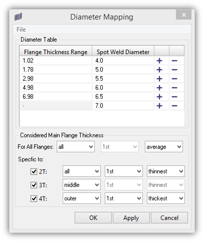
What has been formerly known as DvsT is the Diameter Mapping Table now. This table can be accessed from all ACM spot weld panels, when the diameter is not directly assigned. In the table the user can describe how the main flange thickness is recognized. The main flange thickness decides about the finally used ACM diameter. The thickness ranges can directly be modified in the table and a diameter mapping file can be saved from this window. When realizing ACMs the finally used diameter is written to each single connector.
|
A new area connector realization type for the RADIOSS user profile has been added. This realization performs a typical hexa adhesive connection with contact definition.
|
Geometry
A new "skin offset" midsurface extraction method has been added. This method generates a midsurface by duplicating and offsetting the inner skin surfaces and assigning a constant thickness. This is useful for parts where there is a constant thickness with no t-connections expected in the final result. This is significantly faster than other midsurface extraction methods, but is focused only on this specific model class.
|
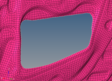
A new tool has been added to the Midsurface panel for imprinting solid features to the midsurface. This is useful when the midsurface does not properly represent solid features like pockets, thickness transitions, etc. Imprints can be made in multiple ways to accurately capture these features.
|
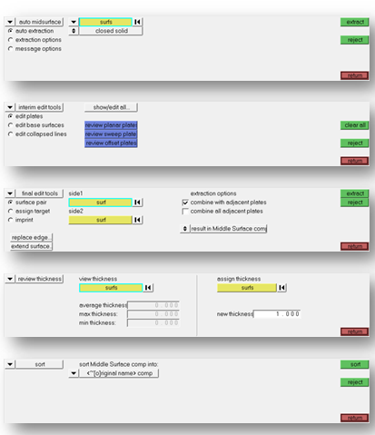
The Midsurface panel has been reorganized, with attention paid to the most common workflows. Tools have been separated logically into subpanels, with shortcuts to other relevant panels added. New options to control the behavior of warning messages have also been added. Enhanced sorting behavior has also been adopted. Components created for sorting now automatically inherit their parent component’s attributes (color, card image, material, property, etc.) and are organized into the same assembly/include/module structure. A new sort mode has been added to create incrementally named components, based on the parent component name. Finally, it is now possible to immediately sort the midsurfaces after extraction, instead of requiring a second manual step.
|
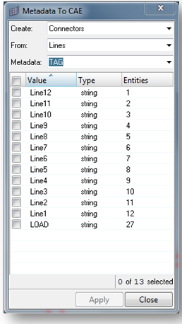
Metadata is now propagated when performing most geometry editing operations, and certain geometry creation operations (duplicate, spline/trimmed surfaces from free lines). This allows for metadata to be duplicated and combined during relevant operations, leading to improved automation and scripting capabilities.
|
|
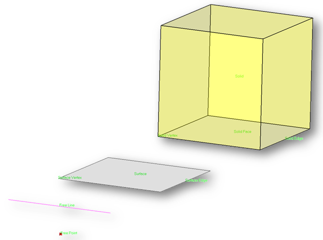
All geometric entities are now supported for creation of HM tag entities.
|
This tool has been enhanced to support the creation of regions.
|
|
Meshing
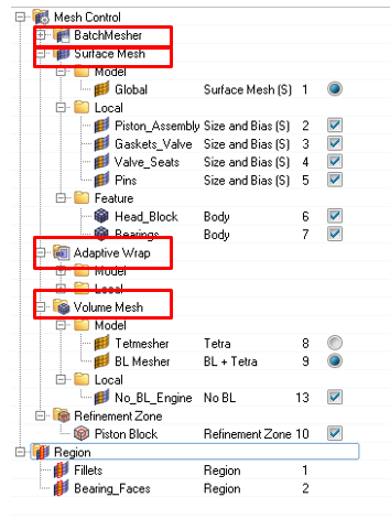
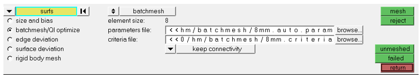
A new browser-based workflow for meshing has been implemented. This workflow utilizes the new "mesh control" entity. This new entity:
The following meshing algorithms are available:
|
|
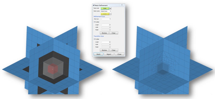
The ability to refine shell elements by pattern within a cube is now possible. A target mesh size, along with a refinement box and a transition box, are input.
|
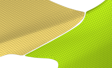
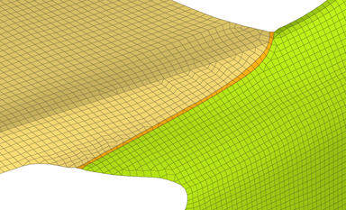
The workflow for adjusting element and surface normal has been significantly improved. The panel has been redesigned to aid in a more streamlined workflow, adding capabilities to adjust entities more efficiently and with better performance.
|
|
||||||||||||||
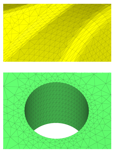
Improvements have been made to the Acoustic Cavity mesher and workflow:
|
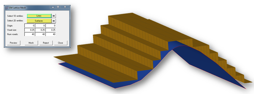
A new tool has been added for generating EM lattice meshes.
|
|
APIs
|
|
A new, consolidated suite of APIs has been added for detecting and reporting information about holes in both geometry and FE.
|
|