HyperWorks Release Notes

AcuSolve 14.0 Release Notes

AcuSolve 14.0 Release Notes

Previous topic This is the last topic Expand/collapse all hidden text  

AcuSolve 14.0 Release Notes

Previous topic This is the last topic JavaScript is required for expanding text JavaScript is required for the print function  

Highlights


The 14.0 release of the AcuSolve product suite continues to build on Altair's class leading solver technology. The latest release of the software delivers new technologies to expand capabilities and improve usability. The 14.0 release provides improvements to AcuSolve's moving mesh technology, new multiphysics coupling in the form of finite mass particle tracing, revised turbulence models, newly developed tutorials, an expanded validation manual, and many other enhancements. In addition to these new features, a number of critical bugs have been addressed in this release, further improving the quality of the product for end users. The details of the release are provided in the following sections.


hmtoggle_arrow1Finite Mass Particle Tracing Using AcuSolve and AcuTrace

AcuTrace has been enhanced to support tracing of spherical particles having finite mass.  When exercising this option, the particle velocity is no longer governed solely by the local flow velocity.  The motion of the particle is computed by solving a conservation equation that incorporates the mass of the particle, the pressure force, the drag force, the viscous stresses, and the virtual mass force.  The user is given control over which terms in the conservation equation should be included at run time and various drag laws are available to choose from.  Wall/particle interactions are handled with user-specified coefficients of restitution to define the energy loss as a result of the collision.

In addition to supporting finite mass particle tracing, the bi-directional coupling between AcuSolve and AcuTrace also provides support for momentum exchange.  For the case of bi-directionally coupled finite mass particle tracing, the effect of the particle's presence appears in the AcuSolve flow field.  The momentum of each particle is computed, and the corresponding reaction force is added to AcuSolve as a source term in each element that the particle passes through.

acusolve_14_001

acusolve_14_002

Finite mass particles in suspension within a mixing tank

Buoyant particles rising in a tube

Note that particles are limited to idealized, spherical shapes in the current release, and the particles are assumed to constitute a dilute and disperse phase within the fluid.  In addition to this, particle-particle collisions are not yet supported.  As a general guideline for use, it is suggested that the ratio of particle spacing to particle diameter should be on the order of 10 or greater for massless particles and on the order of 100 or greater for finite mass particles.

Common applications for finite mass particle tracing include fluidized bed simulations and other applications involving the transport of small particulates within a flow field.


hmtoggle_arrow1Revised Implementation of SST and k-omega Turbulence Models

The 14.0 release contains major improvements to the SST and k-omega turbulence models within AcuSolve.  The new formulation improves the accuracy and robustness of the models by incorporating a change of variables for the omega equation.  Instead of solving for the standard k and omega equations, the new formulation solves for k and clip0010.  The change of variables does not alter the results produced by the underlying turbulence model, but does have significant benefits with respect to numerical robustness.  The new formulation has vastly improved near wall behavior; having a much more agreeable wall boundary condition of 0.0 for the omega transport equation, as well as the ability to be managed easier through wall functions.  Internal testing and validation has shown that this change of variables produces far superior behavior of the models in comparison to past releases.

acusolve_14_003

acusolve_14_004

SST results showing flow over a rail car

A comparison of convergence rate between turbulence models for the rail car

The new models are fully compatible with input files created in older versions of the code.  The nodal initial conditions and boundary condition values are still specified in terms of the eddy_frequency variable.  All conversions to the newly introduced transport quantity ( clip0011) are handled automatically.  The new transport quantity (sqrt_eddy_period) will appear in nodal field outputs along with the kinetic_energy and eddy_frequency variables.  

The revised implementations of SST and k-omega are complete with support for wall functions and wall roughness.  Internal testing has shown that a stretch ratio of 1.3 provides optimal results when using wall functions.

It should be noted that the most efficient solution strategy for these models involves iterating multiple times on the turbulence variables for every iteration of the flow equations.  AcuSolve's AUTO_SOLUTION_STRATEGY command has been updated to reflect this solution strategy.


hmtoggle_arrow1New Mesh Quality Metric (MQM) Technology Added to ALE Mesh Motion

AcuSolve's Arbitrary Lagrange-Eulerian (ALE) mesh motion technology has historically been based on a hyperelasticity model to control the deformation of the mesh.  Using this approach, the stiffness of a given element is assigned based on the proximity to the motion.  In general, this leads to behavior where the elements closest to the motion exhibit high levels of deformation regardless of their size.  In many cases, this formulation leads to undesirable results.  A new method of computing the motion of the mesh has been introduced in AcuSolve V14.0.  Using the new formulation (i.e. Mesh Quality Metric or MQM), the mesh deforms in such a manner as to maintain the original shape of each element.  Each time the boundaries of the simulation are deformed, the mesh is updated using an algorithm that attempts to optimize the quality of the mesh.  The original shape of the elements is used as the reference for which the mesh was assumed to be of optimal quality.  In practice, this method has a number of benefits over the hyperelastic model.  This technique implicitly retains the shape of elements within the boundary layer, which reduces user burden to constrain near wall nodes to move with deforming surfaces.  Additionally, this method inherently moves large deformations to the larger elements in the domain.  Even with ~5000:1 aspect ratio elements near a deforming wall, the MQM approach retains the structure of the boundary layer elements while absorbing the deformation in the far field elements.  See the images below for an example of the behavior of MQM.  Note that the hyperelastic model required constraints on the boundary layer elements to deform to the level shown, whereas the MQM approach handled the boundary layer elements without additional constraint.

acusolve_14_005

acusolve_14_006

The mesh deformation predicted by hyperelastic mode

Mesh quality metric


hmtoggle_arrow1Support for Mixed Topology Surfaces and Volumes

AcuSolve V14.0 now supports the definition of surfaces and volumes using mixed element topology.  In previous releases of the solver, it was necessary to specify all input commands such that only a single parent element set and element type were referenced by each command.  This restriction has been eliminated with the 14.0 release and all solver input commands are functional using the mixed topology input.

Support for the mixed topology input is achieved through the introduction of the SURFACE_SET and VOLUME_SET commands.  With these commands in place, it is now possible to read in the individual surface and volume definitions for later reference in the input file.  Surface sets or volume sets of different topology may then be referenced in a single solver command.

acusolve_14_007

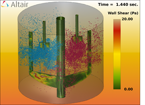
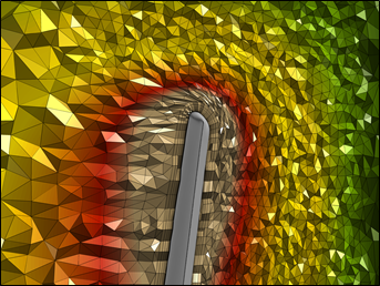
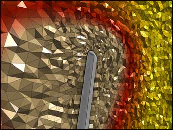
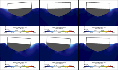
Illustration of mixed topology surface input in AcuSolve.

For example:


# +----------------------------------------------------------------------+

# | Surface sets                                                         |

# +----------------------------------------------------------------------+

SURFACE_SET( "inflow tri3 Fluid wedge6" ) {

   surfaces                            = Read("MESH.DIR/inflow.tri3.ebc.B" )

   shape                               = three_node_triangle

   volume_set                         = "Fluid wedge6"

}

SURFACE_SET( "inflow quad4 Fluid brick8" ) {

   surfaces                            = Read( "MESH.DIR/inflow.quad4.ebc.B" )

   shape                               = four_node_quad

   volume_set                         = "Fluid brick8"

}


# +----------------------------------------------------------------------+

# | Simple Boundary Condition                                            |

# +----------------------------------------------------------------------+

SIMPLE_BOUNDARY_CONDITION( "inflow" ) {

   surface_sets         = {"inflow tri3 Fluid wedge6","inflow quad4 Fluid brick8"}

   type                 = inflow

   inflow_type          = average_velocity

   average_velocity     = 1.0

}

SURFACE_OUTPUT( "inflow" ) {

   surface_sets         = {"inflow tri3 Fluid wedge6","inflow quad4 Fluid brick8"}

   integrated_output_frequency = 1

}

This new capability represents a significant change to the architecture of AcuSolve and is being released in phases.  This first release includes support for all solver commands in the AcuSolve input file, and full post-processing support in AcuTrans, AcuFieldView, AcuProbe, and HyperView.  The new input file format is currently not supported by AcuConsole, HyperMesh, AcuTrace, or AcuFwh.  Support for the new format will be added to the remaining programs in a future release.  Note that AcuSolve continues to support the older, single topology format for all commands as well.  As such, full backward compatibility is retained.


hmtoggle_arrow1Introduction of the AcuSolve Tutorials

The AcuSolve installation now comes equipped with tutorials that provide detailed instructions for getting started with the code and working with some of the more commonly used features.  The purpose of the document is to provide self contained sets of exercises and instructions for both new and experienced users of the software.  The tutorials provide a brief overview of each simulation that is covered, along with the instructions on how to properly set the model up.  All prerequisite files necessary to perform the simulations are included.  The instructions within each tutorial include details on the meshing, solver settings, as well as post-processing of the model.  

As with other AcuSolve documentation, the tutorials are available from the AcuSolve Help Welcome page.  All files necessary to run the simulations that are described in the document are available in the distribution within the following directory: <installation_directory>/model_files/tutorials/AcuSolve>.  The current version includes 5 tutorials, ranging in complexity from steady, isothermal flow to externally coupled multi-physics applications.  Additional tutorials will be added in future releases of AcuSolve.

acusolve_14_008

acusolve_14_009

AcuSolve Help Welcome Page showing links to the AcuSolve tutorials  

Results from the translating check valve tutorial


hmtoggle_arrow1Addition of Smoothing to Interpolated Mesh Motion

A newly developed smoothing algorithm has been added to interpolated mesh motion (MMI).  The impact of smoothing is to improve the behavior of MMI when the background mesh introduces local oscillations in the displacement in the mesh.  This option reduces the likelihood of elements collapsing and also smooths the overall displacements that are enforced by MMI.  It should be noted that this feature does have some additional implications.  Under these conditions, the interpolated mesh motion algorithm is allowed to modify the position of any node that has MMI applied to it.  For degrees of freedom that are not entirely constrained by the MMI, the smoothing algorithm can modify the position.  For example, the behavior of mesh_displacement_type = slip is now different for surfaces that are part of an element set that contains an interpolated mesh motion.  The unconstrained degrees of freedom (in the wall parallel direction) are now controlled by the smoothing algorithm and can have non-zero displacement.


hmtoggle_arrow1Separation of Mesh Motion Constraints from Simple Boundary Condition Commands

AcuSolve's SIMPLE_BOUNDARY_CONDITION command was developed as a mechanism to automate the application of suitable constraints to represent common types of physics.  Inlets, walls, and outlets are examples of the common physics that are addressed by SIMPLE_BOUNDARY_CONDITION.  As part of this command, the constraints that dictate the mesh motion were also added.  Although this does provide a convenient way of assigning constraints, it can introduce some restrictions in flexibility.  To alleviate this, a new command has been created that separates the mesh motion constraints from the SIMPLE_BOUNDARY_CONDITION command.  The new command, MESH_BOUNDARY_CONDITION, provides a centralized mechanism for assigning mesh motion constraints that were previously associated with the SIMPLE_BOUNDARY_CONDITION, FREE_SURFACE, and EXTERNAL_CODE_SURFACE commands. To accomplish this, AcuPrep internally creates a table of constraints for each element face/node on the boundaries and identifies conflicts within the mesh motion boundary conditions.  These conflicts may arise due to combinations of MESH_BOUNDARY_CONDITION and the legacy commands that provide similar functionality.  In the case of conflicting constraints that have equal precedence values, the MESH_BOUNDARY_CONDITION is given priority.  If the precedence values are not equal, then the higher precedence constraint is enforced.  AcuPrep also checks for compatibility of the mesh motion boundary conditions on each node with the boundary conditions applied for the physics through the SIMPLE_BOUNDARY_CONDITION command.

An example showing how to use the newly introduced command to define a planar_slip mesh motion constraint is as follows:

MESH_BOUNDARY_CONDITION ( "slip wall" ) {

surface_sets

= {"tri faces","quad faces"}

type

= planar_slip

}

The introduction of the MESH_BOUNDARY_CONDITION command deprecates the FREE_SURFACE and EXTERNAL_CODE_SURFACE commands.  In addition to consolidating commands, the MESH_BOUNDARY_CONDITION implementation contains more complete error checking.  Surfaces that are defined as planar_slip (equivalent to mesh_displacement_type=slip in SIMPLE_BOUNDARY_CONDITION) are now checked to ensure that a consistent normal direction exists for the entire surface set.  Full details of the command, along with all supported options, are included in the AcuSolve Command Reference Manual.

The MESH_BOUNDARY_CONDITION command is currently supported within the solver and post-processing programs.  Full GUI support will be added in a future release.  Note that AcuSolve continues to support the legacy commands that provided control over mesh motion boundary conditions.  As such, full backward compatibility is retained.


hmtoggle_arrow1Added Support for Distributed Memory Parallel Runs Across Windows Machines

AcuSolve now supports running in distributed memory parallel mode across multiple Windows hosts.  In the past, this could only be achieved when running on a Windows HPC Server cluster.  This restriction has been lifted, and it is now possible to run in parallel on multiple Windows hosts using Intel MPI, Platform MPI, MS-MPI, and MPICH2.  It should be noted that some set-up work is required to install services and create shared directories.  Please see the HyperWorks Installation manual for further instructions.

As part of this effort, the process of setting up parallel simulations for single host applications has been simplified as well.  It is no longer necessary to install the SMPD daemon for Intel MPI when running in parallel on a single Windows host.


hmtoggle_arrow1Improved CFD Post-processing With AcuFieldView

AcuSolve 14.0 comes equipped with a new version of AcuFieldView that is based on Intelligent Light's most recent release of FieldView.  This release of AcuFieldView provides significant improvements when working with AcuSolve data.  The AcuSolve direct reader has been updated to provide full support for mixed element topology surfaces.  In addition to this enhancement, the performance of the direct reader has been improved dramatically.  The performance improvements have been accomplished through a combination of code changes as well as newly added options that enable the user to skip compute intensive steps that are not necessary for all simulations.  Some of the changes that have been made include an ability to avoid reading of AcuSolve's extended output variables.  Disabling this option alone can improve read times by as much as 2x.  User's have the option to remove duplicate surfaces as well, which brings consistency with AcuTrans.  Please see the AcuFieldView User Guide for full details.

acusolve_14_010

Multiple images displaying custom color maps and a multi-window layout.


hmtoggle_arrow1Other Notable Changes

AcuSolve 14.0 contains a number of other notable changes that are worthy of mention.  A brief description of each is shown below:

Uniformity index has been added as an output quantity.  This quantity is part of surface statistics output.
User defined functions on Windows now automatically recompile at run time if the library corresponding to the requested message passing protocol is not present.
moment_center has been added to AcuTrans to  enable user control of the location about which moments are computed.  In previous releases, the moment was always computed about the global origin.
Added ability to specify viscosity as a function of pressure.
Added support for reading binary mesh files in all supported programs (AcuProj, AcuSif, etc.)
Added center_of_mass output quantity to ELEMENT_OUTPUT command.
Improved the performance and scalability of search algorithm used for INTERFACE_SURFACE command.
Added ability to convert flexible body forces and displacements to table and statistics format using acuTrans.
Added support for slip wall mesh displacement when coupling to MotionSolve.
Added surface names into Patran files created by AcuTherm.
Added ability to define external forces for rigid bodies using user defined functions.
Added support for MS-MPI message passing protocol when running outside of Windows HPC Server environment.
Added -mpiopt command line argument to AcuRun to enable specification of command line arguments to the mpirun command.  The default value is _auto, which reverts to previous behavior.
Speed improvements to AcuTrans and other utilities that access AcuSolve's nodes and elements through the adb API.
Added ability to assign nodal initial conditions based on user defined functions and curve fits.  The NODAL_INITIAL_CONDITION command is now able to have multiple instances for a given variable as well.  This allows assigning initial conditions on different collections of nodes using different approaches.
Added the allow_stagger_reordering option to the TIME_SEQUENCE command to allow AcuSolve to change the stagger order if it determines that changing the sequence of equations will lead to better stability.  Note that this option will only have an effect for problems containing FREE_SURFACE commands at the current time.
Changed the behavior of mesh_displacement_type=slip parameter in the SIMPLE_BOUNDARY_CONDITION command such that only planar surfaces are accepted.
Added the ability to read lists of strings from file for all commands that accept a list argument.  For example, it is possible to read a list of surface sets into the SIMPLE_BOUNDARY_CONDITION command by placing them into a file.


hmtoggle_arrow1Notable Resolved Issues
Resolved a problem with the ALE formulation that could induce significant parasitic velocities on interior nodes.
Updated domain decomposition methods to enforce consistent behavior across Windows and Linux platforms.
Fixed a crash when integrated inflow conditions (inflow_type=mass_flux|average_velocity|flow_rate) were used on a surface with no no-slip walls adjacent to it.
Fixed a bug that produced asynchronous time marching in AcuSolve/MotionSolve co-simulations.
Fixed a bug that caused an assertion when computing turbulent diffusivity when the species stagger is not active.
Fixed a bug that prevented wall_velocity_type=normal from being enforced.
Fixed an overallocation of memory in AcuTherm when using fct=direct.
Fixed a bug that caused spurious results when using the INTERFACE_SURFACE command on prism elements.
Fixed a bug that caused thermal undershoot when viscous heating was active and played a dominant role in the heat transfer.


hmtoggle_arrow1Changes to Supported Platforms and Third Party Packages
Updated Linux kernel to 2.6.18-348
Removed mvapich entirely from installation packages and discontinued support
Updated Intel MPI to version V5.1
Updated Platform MPI to V9.1.2 community edition
Updated MPICH to v3.1.3 on Linux and V1.4.1 on Windows
Updated Microsoft MPI to V5.0.
Rearranged the location of MPI libraries in the distribution to support unification across all Altair solvers.
Discontinued support for mx-mpi and gm-mpi.  This will be the last release for which these executables are shipped.
Removed and discontinued support for Octigabay MPI.
Removed and discontinued support for Cray MPI.
Included redistributable ms-mpi installer package in Win 64 package.


hmtoggle_arrow1Changes in default behavior

The AUTO_SOLUTION_STRATEGY command now solves the mesh stagger first when performing simulations with mesh motion present.


hmtoggle_arrow1Summary of New/Changed AcuSolve Input File Commands

The following table summarizes the changed or newly introduced AcuSolve input file commands.  Note that a full description of each command is available in the AcuSolve Command Reference Manual.

AcuSolve Command Name

Description

MESH_MOTION

Added rigid_body_external_force_type, rigid_body_external_moment_type, and supporting options to enable specification of external forces on rigid bodies using user functions and curve fits.

VISCOSITY_MODEL

Added pressure to the list of available curve_fit_variables.

NODAL_INITIAL_CONDITION

Added type, selection_type, precedence, and supporting options to enable the definition of initial conditions based on user defined functions and curve fits.  Note that initial condition commands can now be applied to a node subset in the model and any number of NODAL_INITIAL_CONDITION commands can be present for a single variable.

VOLUME_SET

Newly created command that is used to read in a collection of volume elements.  The volume set is then referenced from other commands within the input file to provide support for mixed topology volumes.

ELEMENT_SET

Added the volume_set parameter to enable definition of mixed element topologies within a single element set.

ELEMENT_OUTPUT

Added volume_set and type parameters to enable definition of element output on mixed topology element sets.

SURFACE_SET

Newly created command that is used to read in a collection of surface elements.  The surface set is then referenced from other commands within the input file to provide support for mixed topology surfaces.

FAN_COMPONENT

Added surface_sets to enable definition of mixed surface element topologies within a single FAN_COMPONENT command.

HEAT_EXCHANGER_COMPONENT

Added surface_sets to enable definition of mixed surface element topologies within a single HEAT_EXCHANGER_COMPONENT command.

HEAT_EXCHANGER_COMPONENT

Added coolant_temperature and coolant_temperature_multiplier_function to support type=constant_coolant_temperature.

ELEMENT_BOUNDARY_CONDITION

Added surface_sets to enable definition of mixed surface element topologies within a single ELEMENT_BOUNDARY_CONDITION command.

SURFACE_INTEGRATED_CONDITION

Added surface_sets to enable definition of mixed surface element topologies within a single SURFACE_INTEGRATED_CONDITION command.

FREE_SURFACE

Added surface_sets to enable definition of mixed surface element topologies within a single FREE_SURFACE command.

TURBULENCE_WALL

Added surface_sets to enable definition of mixed surface element topologies within a single TURBULENCE_WALL command.

PARTICLE_SURFACE

Added surface_sets to enable definition of mixed surface element topologies within a single PARTICLE_SURFACE command.

RADIATION_SURFACE

Added surface_sets to enable definition of mixed surface element topologies within a single RADIATION_SURFACE command.

SOLAR_RADIATION_SURFACE

Added surface_sets to enable definition of mixed surface element topologies within a single SOLAR_RADIATION_SURFACE command.

INTERFACE_SURFACE

Added surface_sets to enable definition of mixed surface element topologies within a single INTERFACE_SURFACE command.

GUIDE_SURFACE

Added surface_sets to enable definition of mixed surface element topologies within a single GUIDE_SURFACE command.

INTERPOLATED_MOTION_SURFACE

Added surface_sets to enable definition of mixed surface element topologies within a single INTERPOLATED_MOTION_SURFACE command.

EXTERNAL_CODE_SURFACE

Added surface_sets to enable definition of mixed surface element topologies within a single EXTERNAL_CODE_SURFACE command.

SIMPLE_BOUNDARY_CONDITION

Added surface_sets to enable definition of mixed surface element topologies within a single SIMPLE_BOUNDARY_CONDITION command.

SIMPLE_BOUNDARY_CONDITION

Added temperature_coupling_type to allow specification of the method used to couple the thermal fields between AcuSolve and an external code.

SURFACE_OUTPUT

Added surface_sets to enable definition of mixed surface element topologies within a single SURFACE_OUTPUT command.

MESH_BOUNDARY_CONDITION

Newly created command that is used to define the mesh motion constraints on a given surface.  This command houses the collection of mesh motion boundary conditions from the SIMPLE_BOUNDARY_CONDITION, FREE_SURFACE, and EXTERNAL_CODE_SURFACE commands.


hmtoggle_arrow1Summary of Deprecated AcuSolve Input File Commands

The following table summarizes the AcuSolve input file commands that are deprecated in this release.  Support will continue for legacy input files, but users should migrate their modeling process to leverage the new commands when possible.

AcuSolve Command Name

Comments

FREE_SURFACE

Deprecated by the MESH_BOUNDARY_CONDITION command

EXTERNAL_CODE_SURFACE

Deprecated by the MESH_BOUNDARY_CONDITION command


hmtoggle_arrow1Summary of New/Changed AcuSolve Command Line Options

The following table summarizes the changed or newly introduced AcuSolve command line arguments.  Note that a full description of each option is available in the AcuSolve Programs Reference Manual.

Program

Option

Description

AcuRun

-install_smpd

Added support for the installation of message passing daemon service for Platform MPI.  This is needed only when using distributed memory parallel operation across multiple Windows hosts.

AcuRun

-translate_output_to

Added an option of h3d as a supported output format at the conclusion of the run.

 
AcuRun
AcuRunTrace
AcuRunFwh

-message_passing_type

Removed mvapich, octigabay, and cray mpi support.

 
AcuRun

-view_message_passing_type

Removed mvapich, octigabay, and cray mpi support.

 
AcuRun
AcuRunTaceAcuRunFwh

-mpirun_options

New option that allows passing of options directly to the mpirun/mpiexec command.

AcuRun
AcuRunTrace
AcuRunFwh

-automount_path_remove

Changed default setting to _none.

AcuRun
AcuRunTrace
AcuRunFwh

-automount_path_name

Changed default setting to _none.

AcuSolve

-projection_eigenvalue_type

New option that provides control over algorithm used to compute eigenvalues in the linear solver.

AcuSolve

-linear_solver_error_output

New option that provides control over whether debug information should be output when an error is encountered in the linear solver.

AcuSolve

-mqm_reference_push_factor

New option that provides control over whether the reference coordinates or the current coordinates should be used when computing the mesh quality metric for moving mesh simulations that use ALE.

AcuSolve

-num_mmi_smoothing_passes

New option that provides control over the number of smoothing passes used for interpolated mesh motion constraints.

AcuSurf

-coordinates_file,
-connectivity_file_list,
-surface_file_list,
-surface_node_file_list

Added ability to read binary format for all mesh files.

AcuMesh2Tet

-coordinates_file,
-connectivity_file_list,
-surface_file_list,
-periodic_bc_file_list

Added ability to read binary format for all mesh files.

AcuProj

-coordinates_file

Added ability to read binary format coordinates files.

AcuPbc

-coordinates_file,
-nodal_bc_1_file,
-nodal_bc_2_file

Added ability to read binary format for all mesh files.

AcuPev

-coordinates_file,
-node_file_list,
-surface_file_list

Added ability to read binary format for all fluid mesh files.

AcuSurf

-coordinates_file,
-connectivity_file_list,
-surface_file_list,
-surface_node_file_list

Added ability to read binary format for all mesh files.

AcuTrans

-moment_center

New option that enables specification of which point moments are computed about for surface outputs.

AcuTrans

-moment_center_mesh_motion

New option that enables specification of a mesh motion to use when computing moments about a given location.

AcuTrans

-flexible_body_output

New option that controls the export of FLEXIBLE_BODY results.

AcuTrans

-flexible_body_output_vars

New option that controls the variables to export for the FLEXIBLE_BODY.

AcuTrans

-flexible_body_output_sets

New option that controls the FLEXIBLE_BODY output sets to convert.

AcuRunTrace

-file_format

New option that controls the internal file format.

AcuTherm

-num_temperature_filter_passes

New option controlling the number of filter passes on the temperature.

AcuTherm

-num_reference_temperature_filter_passes

New option controlling the number of filter passes on the reference temperature.

AcuTherm

-num_film_filter_passes

New option controlling the number of filter passes on the film coefficient.

AcuTherm

-num_heat_filter_passes

New option controlling the number of filter passes on the heat flux.

AcuTherm

-film_calculation_type

New option controlling the type of calculation to use for computing the reference temperatures and heat transfer coefficients.

AcuTherm

-limit_reference_temperature

New option controlling whether the reference temperature should be limited to the peak nodal temperature in the model.