HyperWorks Release Notes

MotionSolve 14.0 Release Notes

MotionSolve 14.0 Release Notes

Previous topic Next topic Expand/collapse all hidden text  

MotionSolve 14.0 Release Notes

Previous topic Next topic JavaScript is required for expanding text JavaScript is required for the print function  

Highlights


MotionSolve is a state-of-the-art multi-body solver available in HyperWorks. It has a complete set of modeling elements and powerful numerical methods to support a full set of analysis methods. The accuracy, speed and robustness of MotionSolve have been validated through extensive testing with customer models and test data. MotionSolve also offers unmatched compatibility with ADAMS/Solver input.

The major highlights of the 14.0 release are listed below.

Revamped 3D rigid body contact solution that improves robustness, accuracy and performance
Non-linear finite element bodies are introduced in MotionSolve (beta release)
Geometric stiffening support is added for linear flexible bodies
A new Python Lexicon is available for model building
Several enhancements to Linear Analysis


hmtoggle_arrow1Improved 3D Rigid Body Contact Solution

3D contact in MotionSolve has been revamped. Described below are the pertinent changes to the solver:

Change

Benefit

A new mesh-mesh collision engine has been implemented

The robustness of models making use of mesh-mesh contact improves significantly. The accuracy and performance have also been seen to be superior to the collision engine used in v13.0.

Contact simulations are parallelized by default in MotionSolve

The run time of simulations containing many contact forces has been seen to decrease significantly, with speedups of about 5x seen in some cases.

Special handling of primitive spheres as colliding geometries

When your model contains contact elements that make use of primitive spherical geometry (a sphere that is not meshed), MotionSolve automatically switches to a more efficient, analytical or semi-analytical collision engine.

The advantage of doing this is that the simulation time can be reduced by as much as 7x.

Initial penetrations are monitored to get the exact point of first contact

A zero crossing sensor that monitors the distance between contacting geometries is now available. The zero crossing sensor controls integrator step-size to precisely capture the contact event.

By doing this, large initial penetrations leading to unrealistic system behavior are avoided.

Note: This sensor is only meaningful for impulsive contacts. If a contact is persistent, then a zero crossing sensor is not needed

New contact force model

A new “Volume” force model that relies on understandable physical parameters such as bulk modulus and shear modulus is now available. This means that contact parameters have a physical basis and can be easily defined.

Contact outputs are written to the output files at times when the penetration depth is maximum

An option to output the system state at the maximum penetration depth in-between two regular output steps is now available. When you run a simulation from MotionView, this is done automatically. You can filter out these “extra” outputs in HyperView.

Enhanced CONTACT() function

The CONTACT() function has been enhanced to provide many more details about the contact such as maximum penetration depth, number of contact patches, total number of contacts, area of contact, etc.

Contact overview table is printed at the end of the simulation

Contact metrics tables are now printed in the MotionSolve log file. You can examine the metrics table to determine what the maximum penetration(s) and normal force(s) is/are in your model and when it occurred. Two tables are printed – one ordered by maximum penetration depth and another ordered by maximum contact force:

ms_14_01

hmtoggle_arrow1Non-linear Finite Element Bodies in MotionSolve (beta release)

MotionSolve 14.0 includes a beta release of the “NLFE Body” which allows you to model non-linearly flexible components in your multibody system. The NLFE Body is based on the Absolute Nodal Coordinate Formulation (ANCF). Nonlinearity can occur for two main reasons: (A) Geometric nonlinearity and (B) Material non-linearity. The NLFE body supports both.

A non-linear modeling component is typically required in the following scenarios:

A large deformation is expected in the flexible component, or an unusually large deformation is observed in the flexible component
Stresses in your flexible components approach yield point of the material
The flexible component is composed of non-linear hyper elastic materials like rubber or polyurethane. The material exhibits a nonlinear stress vs. strain behavior or is hyper elastic
A linearly flexible modelling component does not provide the fidelity that is desired

NLFE subsystems are included in MotionSolve as a flexible body that is specified through an ANCF XML file. The MotionSolve XML file fragment below illustrates this.

ms_14_02

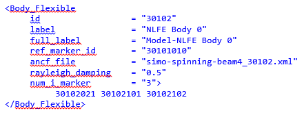
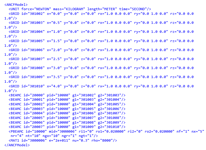
The NLFE subsystem can consist of any combination of atomic MotionSolve NLFE elements. For the example shown above, the NLFE subsystem is specified in the file simo-spinning-beam4_30102.xml. The contents of this file are shown in the table below.

ms_14_03

MotionSolve supports a comprehensive set of NLFE modeling elements. The table below summarizes the current implemented atomic NLFE entities in MotionSolve. Note, that MotionView supports only a small subset of these. You can use these in a MotionView model by using a Templex template.

Element Type

Supported Element Set

Line Elements

BEAM9        (Gradient Deficient ANCF Beam Element)

BEAMC        (Beam Element with Circular Cross Section)

BEAM12        (Fully Parameterized ANCF Beam)

CABLE        (Cable Element)

Surface Elements

QUAD12        (Rectangular Thick Plate Element)

QUAD9        (Rectangular Thin Plate Element)

TRIA12          (Triangular Thick Plate Element)

TRIA9            (Triangular Thin Plate Element)

Solid Elements

HEXA12          (C1 Brick Solid Element)

HEXA3            (C0 Brick Solid Element)

PENTA12        (C1 Penta Solid Element)

PENTA3          (C0 Penta Solid Element)

TETRA12        (C1 Tetra Solid Element)

TETRA3          (C0 Tetra Solid Element)

Scalar and Bushing Elements

ABUSH        (Bushing Element)

LINE2          (Two nodes line spring element)

LINE3                 (Three nodes line spring element)

LINE4          (Four nodes line spring element)

Mass Elements

CONGM        (Concentrated mass element connection)

CONPM        (Concentrated point mass)

Connector Elements

CONN0        (Connector element)

CONN1        (Connector element)

CONN2        (Connector element)

CONN3        (Connector element)

Linear Elastic Material Models

MAT1                (Continuum Mechanics Approach )

MAT1LS        (Linear Strain Material Model)

MAT6                (Elastic Line Approach)        

Hyper-Elastic Material Models

MAT2                (Incompressible Neo-Hookean Material Model)

MAT3                (Compressible Neo-Hookean Material Model)

MAT4                (Mooney-Rivlin material model)

MAT5                (Yeoh material model)

Anisotropic Material Model

MAT7                (Thin Plate Element Anisotropic Material Model)

MAT7ORT        (Thin Plate Element Orthotropic Material Model)

MAT9                (Anisotropic Material Model)

MAT9ORT        (Orthotropic Material Model)

MAT9TRA        (Transverse Isotropic Material Model)

Geometric Properties

PABUSH        (Bushing element properties)

PBEAM9        (Arbitrary Cross Section Beam element properties)

PBEAMA        (Arbitrary Cross Section Beam element properties)

PBEAMC        (Circular beam element properties)

PBEAML        (Property card of the ANCF beam elements)

PCABLE        (Cable element properties)

PLINE                (Line spring property)

PSHELL        (Plate elements properties)

PSOLID        (Solid elements properties)

Other Inputs

GRID

UNITS

For more information about these elements, you may refer to the NLFE Reference Manual.

MotionSolve also writes out a 3D representation of the BEAM and CABLE elements that can be animated in HyperView. Displacement, stress and strain contours can be visualized on the NLFE body. Other operations such as section cuts can also be applied.

For more details, please refer to the MBS solution release notes. Also, please note that this capability is being offered as a beta or experimental feature and is not expected to be used in a production environment.