Introduction
In OptiStruct, structural models involving contact are solved by using Small Displacement Nonlinear Analysis. The analysis involves finding the contact status, such as contact clearance and pressure. Contact clearance spans the distance between the master and slave, while contact pressure is developed between two surfaces in contact.
The traditional thermal structural analysis is one-way coupling, in the sense that thermal analysis influences structural analysis by providing temperature, but structural problem does not affect the thermal problem.
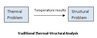
Figure 1: Traditional Thermal-Structural Analysis – Thermal results affect the structural problem
When contact problems are involved, thermal structural analysis becomes fully coupled since contact status changes thermal conductance.
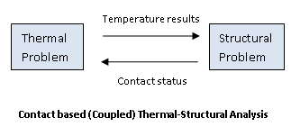
Figure 2: Contact-based (Coupled) Thermal-Structural Analysis – Contact status affects the thermal problem
In Figure 1, you can see that a change in contact status does not affect the thermal problem. This may lead to inaccurate solutions if thermal conductance depends on the contact status. In Figure 2, the contact clearance and/or pressure changes during the course of the quasi-static nonlinear analysis, the corresponding change in the thermal conductance will affect the solution of the thermal problem.
Thermal Contact Solver
An iterative solution process is developed to solve fully coupled nonlinear thermal structural problem, as shown in Figure 3. Thermal analysis is performed first using initial contact status. Nonlinear structural analysis is employed to find contact status. Thermal conductance at the contact interface is calculated based on contact clearance or pressure or based on user-defined values. Coupling is essential because the contact status is used to determine thermal conductance. Temperature results from thermal analysis are used as convergence criteria.
Thermal conductance across contact interface can be based on user-defined values, clearance, or pressure. The PGAPHT and PCONTHT entries can be used to define the thermal conductivity values.
Note:
| 1. | For thermal contact problems with CGAP/CGAPG, PGAPHT is required. The PGAPHT entry should have the same PID as PGAP. For problems with CONTACT and PCONT, the PCONTHT entry should be used and it requires the same PID as PCONT. |
| 2. | Thermal conductivity based on the AUTO option (KCHTC/KAHT fields on PCONTHT/PGAPHT entries) can be used in thermal analysis to allow OptiStruct to automatically determine the conductivity values based on the conductivity of surrounding elements. AUTO conductivity is chosen in such a way that it works as a perfect conductor for closed gap/contact and insulator for open gap/contact. |
| 3. | For problems without PCONT, PCONTHT is not required. Thermal conductivity is internally calculated by the AUTO method. |
|
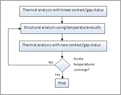
Figure 3: Fully coupled contact-based thermal-structural analysis
Theoretically, while higher conductance values enforce a perfect conductor, excessively high values may cause poor conditioning of the conductivity matrix. If such effects are observed, it may be beneficial to reduce the value of conductance, or use conductance based contact clearance and pressure.
Clearance based thermal conductance (TCID on PCONTHT/PGAPHT, via TABLED#)
The clearance based conductance values can be specified one the TABLED# entries (which should start from zero clearance). Conductance is linearly interpolated within the range on the TABLED# entry. It is extrapolated to zero outside the range. The typical conductance values vary as follows:
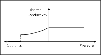
Figure 4: Thermal conductance based on contact clearance
Pressure based thermal conductance (TPID on PCONTHT, via TABLED#)
The pressure based conductance values can be specified one the TABLED# entries. The typical conductivity values vary as follows:
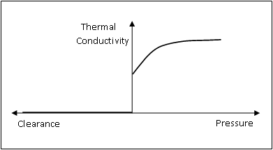
Figure 5: Thermal conductance based on contact pressure
Clearance and pressure based thermal conductance (TCID and TPID on PCONTHT, via TABLED#)
The clearance and pressure based conductance values can be specified on the TABLED# entries. The typical conductance values vary as follows:
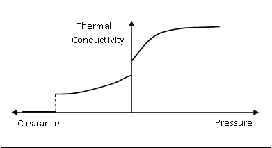
Figure 6: Thermal conductance based on contact clearance and pressure
Typical thermal conductance values increase as the clearance between the master and slave decreases. In the case of contact pressure, the thermal conductance increases with a corresponding increase in pressure.
| Note: | Shell elements are considered to be membranes in Heat Transfer Analysis. Composite properties are homogenized (1 degree of freedom per grid). The temperature distribution through the thickness of shell elements is not calculated. Only nodal temperature is determined. |
Thermal Contact without Static Analysis
Pure heat transfer analysis with thermal contact is solved based on initial contact status. Contact clearance and area are calculated based on geometry. KAHT, KBHT and TCID on PGAPHT card and KCHTC, KOHTC and TCID on PCONTHT card can be used. Contact pressure is not available without static analysis. Therefore, TPID can not be used in such setting.


