HyperWorks Solvers

/GJOINT

/GJOINT

Previous topic Next topic Expand/collapse all hidden text  

/GJOINT

Previous topic Next topic JavaScript is required for expanding text JavaScript is required for the print function  

Block Format Keyword

/GJOINT - Gear Type Joint

Description

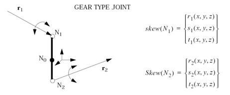
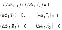
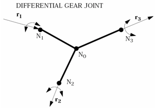
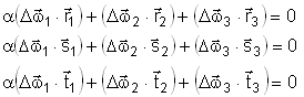
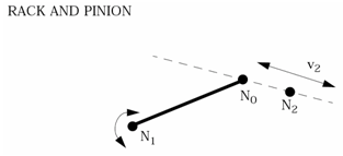
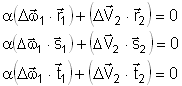
Defines complex (gear-type) joints. This keyword is not available for SPMD computation.

Format

(1)

(2)

(3)

(4)

(5)

(6)

(7)

(8)

(9)

(10)

/GJOINT/type/joint_ID/unit_ID

joint_title

node_ID0

FscaleV

Mass

Inertia

node_ID1

node_ID2

node_ID3

Mass1

Inertia1

r1x

r1y

r1z

Mass2

Inertia2

r2x

r2y

r2z

Mass3

Inertia3

r3x

r3y

r3z

hmtoggle_plus1Flag Definition

Field

Contents

SI Unit Example

type

Type of input

(see table below for available keywords)


joint_ID

Gear type joint identifier

(Integer, maximum 10 digits)


unit_ID

Optional unit identifier

(Integer, maximum 10 digits)


joint_title

Gear type joint title

(Character, maximum 100 characters)


node_ID0

Primary node identifier (position node)

(Integer)


FscaleV

Velocity scale factor

Default = 1.0  (Real)

fail_lad_SI_k

Mass

Added mass to primary node

Default = 0.0  (Real)

symbol_kg_unit

Inertia

Added to primary node inertia

Default = 0.0  (Real)

symbol_kg_m2

node_ID1

Node identifier N1

(Integer)


node_ID2

Node identifier N2

(Integer)


node_ID3

Node identifier N3 - only necessary for differential gear joint.

(Integer)


Mass1

Added mass to node_ID1

Default = 0.0  (Real)

symbol_kg_unit

Inertia1

Added to node_ID1 inertia

Default = 0.0  (Real)

symbol_kg_m2

r1x

Local axis X component

Default = 1.0  (Real)


r1y

Local axis Y component

Default = 0.0  (Real)


r1z

Local axis Z component

Default = 0.0  (Real)


Mass2

Added mass to node_ID2

Default = 0.0  (Real)

symbol_kg_unit

Inertia

Added to node_ID2 inertia

Default = 0.0  (Real)

symbol_kg_m2

r2x

Local axis X component

Default = 1.0  (Real)


r2y

Local axis Y component

Default = 0.0  (Real)


r2z

Local axis Z component

Default = 0.0  (Real)


Mass3

Added mass to node_ID3

Default = 0.0  (Real)

symbol_kg_unit

Inertia3

Added to node_ID3 inertia

Default = 0.0  (Real)

symbol_kg_m2

r3x

Local axis X component

Default = 1.0  (Real)


r3y

Local axis Y component

Default = 0.0  (Real)


r3z

Local axis Z component

Default = 0.0  (Real)


hmtoggle_plus1Complex Joint Types

Type

Description

GEAR

symbol_inf rotational gear

DIFF

symbol_inf differential gear

RACK

symbol_inf rack and pinion

hmtoggle_plus1 Comments
1.Complex (gear-type) joints belong to the family of kinematic constraints treated by a Lagrange multipliers’ method. A joint position is defined by a central node_ID0, which are connected to two or three secondary nodes. Mass and inertia must be added to all nodes. It is advisable to place the primary node in the mass center of the joint. Kinematic constraints impose relations between secondary nodes velocities.

clip0016-1

2.Translational velocities of gear joint nodes are constrained by a rigid link relation. For the rotational DOF, a scale factor is imposed between velocities of node_ID1 and node_ID2, measured in their local coordinates. The corresponding constraint equations are the following:

starter_gjoint_eq

where, clip0259 and clip0260 are relative rotational velocities of node_ID1 and node_ID2 in respect of the rigid body rotational velocity.

clip0017

3.The rotational velocities of a differential gear joint are constrained by the relations:

starter_gjoint_eq2

clip0018

4.The rack and pinion joint allows the rotational velocity of node_ID1 to be transformed to a translational velocity of node_ID2. The constraint equations for these velocities are:

starter_gjoint_eq3

5.This option is not available, if it is applied on:
a node with a null mass
a node with a null inertia (except in case of node_ID2 of a rack type GJOINT)

See Also:

Implicit Features and Compatibility Information