Definition
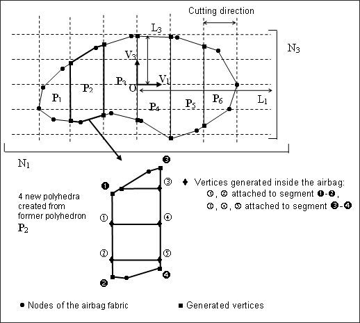
You may define an orthogonal frame (O, V1, V2, and V3), a bounding-box of the airbag fabric to be mesh defined by the lengths (L1, L2, and L3) and the number of cutting-step for each direction (N1, N2, and N3).
The cutting width is then given by:

The image below shows a two-dimensional case of how the airbag fabric is cut:
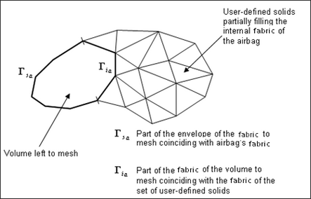
The automatic meshing procedure is also required if the set of user-defined solids (Ibric) does not entirely fill the internal volume of the airbag.
For example, in a case of a folded airbag with a right choice for the cutting direction V1 and V2, meshing may be sufficient:
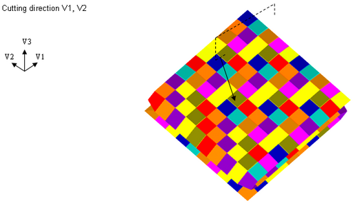
Example 1: Cutting example
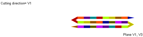
In cases where the injector is modeled with an initial rigid volume (canister), using only two cutting direction (V1 and V3) gives a coarser mesh.
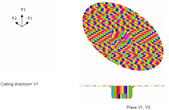
Example 2: Coarser mesh around the inflator
In this example, it may be greater to use the third cutting direction (V2) to reach the following mesh:
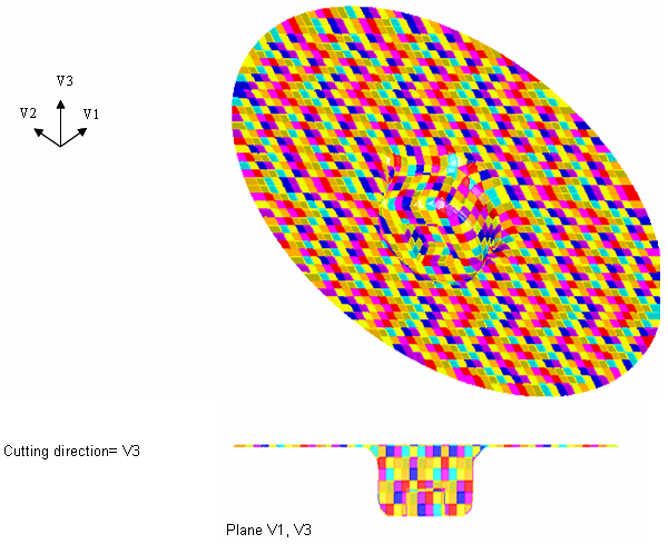
Example 3: Meshing is optimized near the injector due to cutting direction V3


