|
»Click here to display Table of Contents«
|

PBEAML |

|

|

|

|
|
PBEAML |
|
|
|

|
|
»Click here to display Table of Contents«
|
PBEAML |
|
|
|
|
|
PBEAML |
|
|
|
|
Geometric properties Element |
|||||||||||||||||||||||||||||||||||||||||||||||||||||||||||||||||||||||||||||||||||||||
Description |
|||||||||||||||||||||||||||||||||||||||||||||||||||||||||||||||||||||||||||||||||||||||
PBEAML lets you specify the geometric properties for an associated beam element of a specific cross section type. |
|||||||||||||||||||||||||||||||||||||||||||||||||||||||||||||||||||||||||||||||||||||||
Format |
|||||||||||||||||||||||||||||||||||||||||||||||||||||||||||||||||||||||||||||||||||||||
<PBEAML id = "integer" mid = "integer" type = "string" dim1a = "real" dim2a = "real" dim3a = "real" dim4a = "real" dim1b = "real" dim2b = "real" dim3b = "real" dim4b = "real" nx = "integer" ny = "integer" nz = "integer" ngx = "integer" ngy = "integer" ngz = "integer" graph = "integer" /> |
|||||||||||||||||||||||||||||||||||||||||||||||||||||||||||||||||||||||||||||||||||||||
Attributes |
|||||||||||||||||||||||||||||||||||||||||||||||||||||||||||||||||||||||||||||||||||||||
id |
Unique beam property identification number. |
||||||||||||||||||||||||||||||||||||||||||||||||||||||||||||||||||||||||||||||||||||||
mid |
Material property identification number. |
||||||||||||||||||||||||||||||||||||||||||||||||||||||||||||||||||||||||||||||||||||||
dim1a, dim2a, dim3a, dim4a |
Dimensions of the beam at the 1st node of the element. |
||||||||||||||||||||||||||||||||||||||||||||||||||||||||||||||||||||||||||||||||||||||
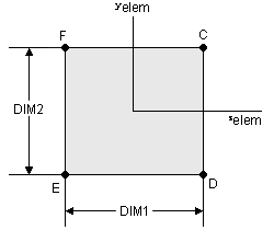
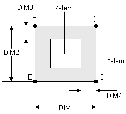
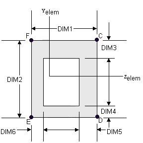
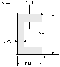
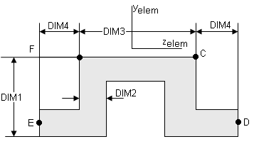
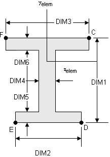
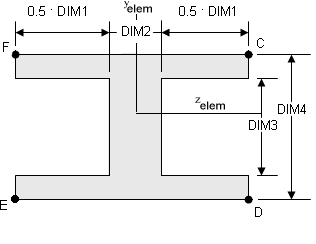
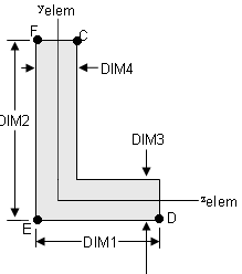
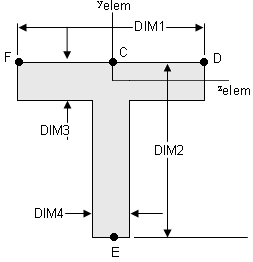
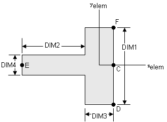
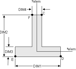
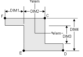
type |
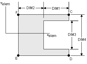
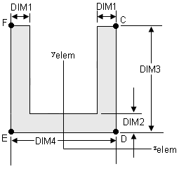
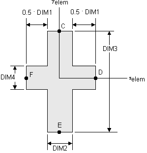
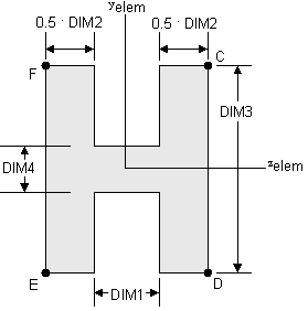
Specifies the type of cross-section for this beam. Choose from the following options: BAR, BOX, BOX1 CHAN, CHAN1, CHAN2, CROSS H, HAT, I, I1, L, T, T1, T2 and Z See Comment 4 for more details on the cross-section types. |
||||||||||||||||||||||||||||||||||||||||||||||||||||||||||||||||||||||||||||||||||||||
dim1b, dim2b, dim3b, dim4b |
Dimensions of the beam at the second node of the element. |
||||||||||||||||||||||||||||||||||||||||||||||||||||||||||||||||||||||||||||||||||||||
nx, ny, nz |
Number of integration points in the X, Y and Z directions. Default for nx is 5, ny is 3 and nz is 3. |
||||||||||||||||||||||||||||||||||||||||||||||||||||||||||||||||||||||||||||||||||||||
ngx, ngy, ngz |
Number of sub-elements in the X, Y and Z directions. The default for all three is 1. See Comment 5 for more details. |
||||||||||||||||||||||||||||||||||||||||||||||||||||||||||||||||||||||||||||||||||||||
graph |
A post-processing flag that determines how this element is represented in the animation H3D. The default is 2. See Comment 5 for more details. |
||||||||||||||||||||||||||||||||||||||||||||||||||||||||||||||||||||||||||||||||||||||
Comments |
|||||||||||||||||||||||||||||||||||||||||||||||||||||||||||||||||||||||||||||||||||||||
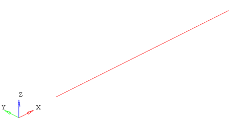
Figure 1: The representation of a beam with graph = 1. Note: When using graph=”0” or graph=”1”, you will not be able to visualize the stress, strain or displacement contours. To do this, use graph=”2” or graph=”3”.
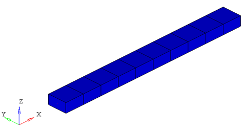
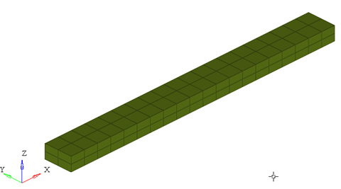
Figure 2: The representation of a beam with graph = 2. The beam is represented by 3D elements
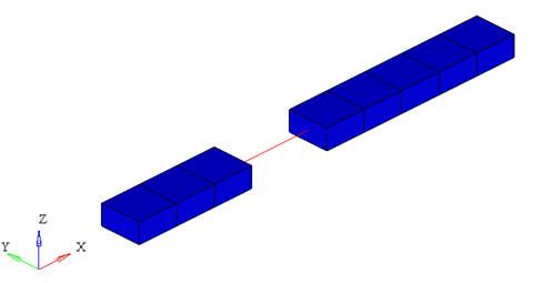
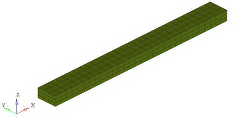
Figure 3: The representation of a beam with graph = 3. The 3D elements in the middle of the beam are turned off to show the center line of the beam When representing the beam as a solid, the arguments ngx, ngy and ngz determine the number of elements that are used to represent the beam in the animation H3D.
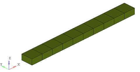
ngx = ngy = ngz = 1
ngx = ngy = ngz = 2
ngx = ngy = ngz = 3 Figure 4: Effect of ngx, ngy and ngz on the 3D representation of a simple beam While increasing the ngx, ngy and ngz results in a better representation of the beam, it also increases the post-processing time taken by MotionSolve to write out the H3D. In addition, large values of ngx, ngy and ngz will increase the file size of the H3D considerably. Consider using the minimum values of these attributes that satisfy your visualization needs. |
|||||||||||||||||||||||||||||||||||||||||||||||||||||||||||||||||||||||||||||||||||||||
Example |
|||||||||||||||||||||||||||||||||||||||||||||||||||||||||||||||||||||||||||||||||||||||
The example demonstrates the definition of a PBEAML property element. <PBEAML id="1" mid="1" type="bar" dim1a="50.0" dim2a="50.0" nx="5" ny="3" nz="3"/> |
|||||||||||||||||||||||||||||||||||||||||||||||||||||||||||||||||||||||||||||||||||||||