Definition
Shell and solid (thick shell) elements are introduced for the coordinate systems.
| • | Global system (X, Y, and Z) |
| • | Natural system (isoparametric frame)  |
| • | Local element coordinate system (x, y, and z) |
4-node Shell Element
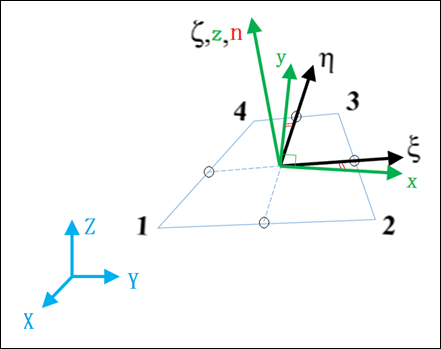
(X, Y, and Z) - Global Cartesian fixed system:
– Natural system (non-normalized coordinate system).
| • | ( ) is from middle point of Line 14 to middle point of Line 23. ) is from middle point of Line 14 to middle point of Line 23. |
| • | (η) is from middle point of Line 12 to middle point of Line 34. |
| • | ( and η) are in the middle surface of shell element and ζ is normal of the middle surface. |
(x, y, and z) – Local coordinate system (orthogonal, normalized elemental coordinate system):
| • | z is normal of middle surface. |
| • | (x and y) are in the middle surface |
| • | x and y are positioned so that they have same angle between z and , y and η |
The origin of and (x, y, and z) are the same as it is at the intersection point of middle point line.
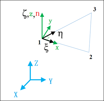
3-node Shell Element
(X, Y, and Z) - Global Cartesian fixed system
– Natural system (non-normalized coordinate system).
| • | is from Node 1 to Node 2. |
| • | η is from Node 1 to Node 3. |
| • | ( and η) are in the middle surface of shell element and ζ is normal of the middle surface. |
(x, y, and z) – Local coordinate system (orthogonal, normalized elemental coordinate system).
| • | z is normal of middle surface. |
| • | x is from Node 1 to Node 2. |
| • | y is orthogonal to x and (x and y) are in the middle surface. |
The origin of and (x, y, and z) are the same as it is at Node 1.
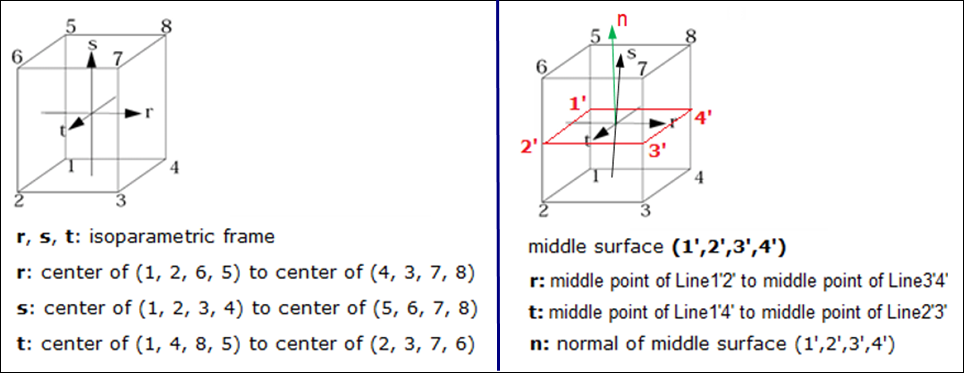
Solids and Thick Shells (hexa)
| • | Global system (X, Y, and Z) |
| • | Natural system (r, s, and t) |
| • | Local element coordinate system (x, y, and z) |
(X, Y, and Z) - Global Cartesian fixed system
(r, s, and t) – Natural system (non-normalized coordinate system).
| • | r is from the center of surface (1, 2, 6, and 5) to center of surface (4, 3, 7, and 8) |
| • | s is from the center of surface (1, 2, 3, and 4) to center of surface (5, 6, 7, and 8) |
| • | t is from the center of surface (1, 4, 8, and 5) to center of surface (2, 3, 7, and 6) |
(r and t) is also in the middle surface (1’, 2’, 3’, and 4’).
| • | r is also from middle point of Line 1' and 2’ to middle point of Line 3’ and 4’. |
| • | t is also from middle point of Line 1’ and 2’ to middle point of Line 3’ and 4’ |
| • | n is normal of middle surface (1’, 2’, 3’, and 4’) |
(x, y, and z) – Local coordinate system (orthogonal, normalized elemental coordinate system).
Local coordinate system in middle surface (1’, 2’, 3’, and 4’) is the same as the local coordinate system in middle surface (1, 2, 3, and 4) for shell element. r in solid is the same as in shell element.
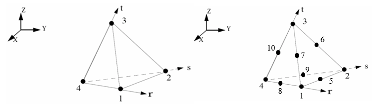
For tetra elements
(r, s, and t) – Natural system (non-normalized coordinate system).
| • | r is from node 4 to node 1 |
| • | s is from node 4 to node 2 |
| • | t is from node 4 to node 3 |
Material System
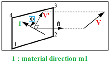
For shell element, anisotropic can be defined with property type 9, 10, 11, 16, 17, and 19, using a material system to describe the anisotropic. Vector V and angle  requested to define material system. (See /PROP/TYPE9 format below ). Material direction (m1 and m2) presents the direction of different mechanic characters (Example: E-Modulus, shear Modulus, stress-strain behavior, damage, …) for anisotropic.
(1)
|
(2)
|
(3)
|
(4)
|
(5)
|
(6)
|
(7)
|
(8)
|
(9)
|
(10)
|
VX
|
VY
|
VZ
|
|
|
|
Use vector V and angle material direction 1 (m1) can be defined (along normal n project vector V to middle surface and get vector V’. Rotate angle of vector V’ then get material direction m1. Material direction m1 is normally the fiber direction). For composite, a different ply could be defined with one vector V and different .
Second material axis m2 is perpendicular to m1 (except for /PROP/TYPE16, angle between m1 and m2 could be defined with  ).
).
| • | n is normal of shell middle surface |
In /PROP/TYPE11, Iorth can determine the relative orientation of the material system.
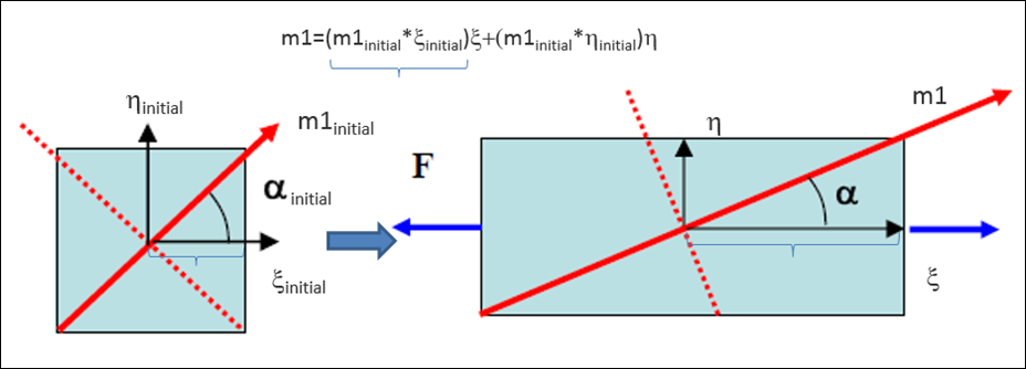
| • | Iorth=0 (default): The orthotropic direction follows the local co-rotational reference. The angle between x and m1 is constant during the simulation. Internal force is computed in local frame and then rotated to the global system. This formulation is more accurate, if a large rotation occurs. |
| • | Iorth=1: The orthotropic direction is attached to the local isoparametric frame. The angle between and m1 is updated during the simulation. It is updated in a way that projection of vector m1 to and η is always constant during the simulation. |
For brick and thick shell elements, use the same process to determine the material direction and orthotropic dirction (Iorth), like shell elements. In /PROP/TYP6 (SOL_ORTH) use the option IP to determine the reference plane.
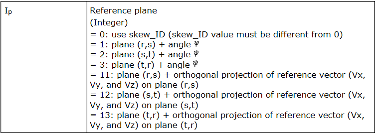
| • | Definition is the same for any Isolid and Iframe parameters |
| • | In the simplest case, material directions m1, m2 and m3 directly with skew (IP =0) are recommended |
| • | For IP > 0 the isoparametric, non-orthogonal system r, s, and t, is used to determine material directions. |
| o | First material axis m1 is determined according to IP. |
| o | The first material axis m1 and m2 is orthogonal and rotated by angle  in the (r’ and s’) plane. in the (r’ and s’) plane. |
| o | The third material axis m3 is normal of m1 and m2 plane (vector product of m1 and m2). |
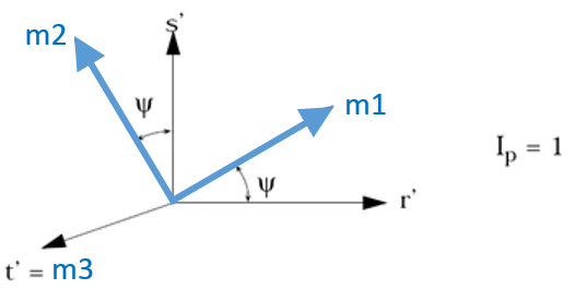
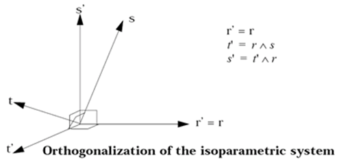
| o | The (r’, s’, and t’) system is orthogonal and it is generated from non-orthogonal isoparametric system (r, s, and t). |
Depending on Isolid and Iframe parameters, three definitions of systems are used in RADIOSS for hexa elements (8-noded bricks) using /PROP/TYPE6 (SOl_ORTH):
Global System Definition
| • | Definition 1: Solids, Isolid=1, 2, 17 + Iframe =0, 1 (default)
Global system is used, no element system (non-co-rotational formulation) available. |
Element System Definition
| • | Definition 2: Solids, Isolid=1, 2, 17 + Iframe=2
Element system (with Iframe=2 co-rotational formulation) is used. |
| • | Definition 3: Solids, Isolid=14 or 24
Iframe parameter has no effect.
Element system is used and co-rotational formulation defined already. |
| Note: | If the co-rotational formulation is used, the orthotropic frame (defined with Iorth) keeps the same orientation with respect to the local (co-rotating) frame, and is therefore also co-rotating. |


