The objective of this tutorial is to simulate Boat Ditching with Boundary Elements to represent continuous water using bi-phase material law (Law 37). In this model, the top chamber is air, lower chamber is water surrounded by boundary elements. Law 37 is used for air, water and boundary. Boundary conditions are applied on each surface of boundary in the normal direction. An interface between fluid and boat (CEL) is defined to manage the contact.
Exercise
Step 1: Load the RADIOSS (Block) User Profile
| 1. | Launch HyperMesh Desktop. |
| 2. | From the Preferences menu, select the User Profiles or click the  icon in toolbar. icon in toolbar. |
| 3. | Select RADIOSS (Block140) and click OK. |
Step 2: Load the boat_ditching_1.hm file
| 1. | From the toolbar, click the Open Model icon  to open the boat_ditching_1.hm file you saved to your working directory from the radioss.zip file. Refer to Accessing the Model Files. to open the boat_ditching_1.hm file you saved to your working directory from the radioss.zip file. Refer to Accessing the Model Files. |
| 2. | Click Open. The model loads into the graphics area. |
Step 3: Define and assign Material, Property to component AIR
| 1. | In the Model browser, right-click and select Create > Material. The new material shows up in the Entity Editor (EE). |
| 3. | For Card Image, select M37_BIPHAS. |
| 4. | Input the values, as shown below. |
Remember to select ALE under ALE CFD Formulation.
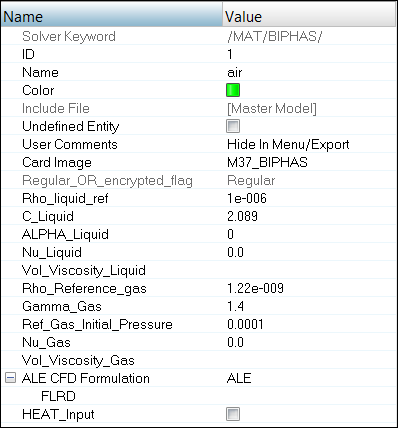
| 5. | Create a new property named Air with a Card Image of P14_SOLID by right-clicking in the Model browser. |
| 6. | Click on the component Air and assign Air as the Prop_Id and air as the Mat_Id in the Entity Editor. |
Step 4: Define and assign Material, Property to component WATER
| 1. | In the Model browser, right-click and select Create > Material. The new material shows up in the Entity Editor (EE). |
| 3. | For Card Image, select M37_BIPHAS. |
| 4. | Input the values, as shown below. |
Remember to select ALE under ALE CFD Formulation.
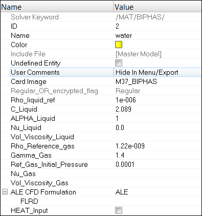
| 5. | In the Model browser, create a new property named Water with a Card Image of P14_SOLID. |
| 6. | Click on the component Water and assign Water as the Prop_Id and water as the Mat_Id in the Entity Editor. |
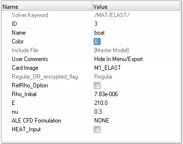
Step 5: Define and assign Material, Property to component BOAT
| 1. | In the Model browser, right-click and select Create > Material. The new material shows up in the Entity Editor (EE). |
| 3. | For Card Image, select M1_ELAST. |
| 4. | Input the values, as shown below: |
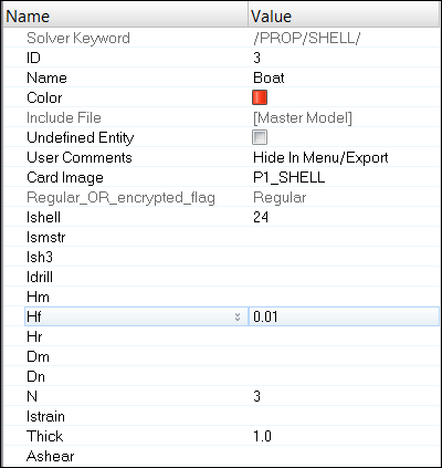
| 5. | In the Model browser, create a new property named Boat with a Card Image of P1_SHELL and assign the new property with the values shown below: |
| 6. | Click on the component Boat and assign Boat as the Prop_Id and boat as the Mat_Id in the Entity Editor. |
Step 6: Define and assign Material, Property to component Air-BC
| 1. | In the Model browser, right-click and select Create > Material. The new material shows up in the Entity Editor. |
| 2. | For Name, enter air-bc. |
| 3. | For Card Image, select M37_BIPHAS. |
| 4. | Input the values, as shown below. |
Remember to select ALE under ALE CFD Formulation.
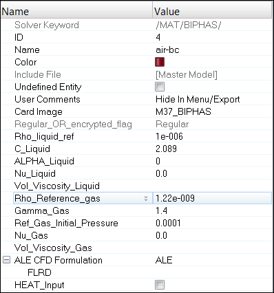
| 5. | Click on the component Air-BC and assign Air as the Prop_Id and air-bc as the Mat_Id in the Entity Editor. |
Step 7: Define and assign Material, Property to component Water-BC
| 1. | In the Model browser, right-click and select Create > Material. The new material shows up in the Entity Editor. |
| 2. | For Name, enter water-bc. |
| 3. | For Card Image, select M37_BIPHAS. |
| 4. | Input the values, as shown below. |
Remember to select ALE under ALE CFD Formulation.
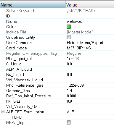
| 5. | Click on the component Water-BC and assign Water as the Prop_Id and water-bc as the Mat_Id in the Entity Editor. |
Step 8: Define an Interface between Boat and Fluid
| 1. | Click Tools > Create Cards > ALE-CFD-SPH > INTER_TYPE18. The new interface opens in the Entity Editor. |
| 2. | For Name, enter Boat-Fluid. |
| 3. | Enter the parameter values, as shown below for Stfval and GAP. |
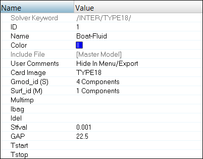
| 4. | Set the Surf_id (M) for master selection to Components and select the boat component. |
| 5. | Set the Grnod_id (S) for slave selection to Components and select all the components, except boat. |
Step 9: Create RBODY for the Boat and assign mass to the Master Node
| 1. | Isolate the boat part using the Model browser. |
| 2. | From the pull-down menu, select Tools > Rbody Manager. |
| 3. | For Title:, enter RIGID-BOAT, verify that Master node: is set to Calculate Node and set Slave node(s): to Parts and select the Boat. |
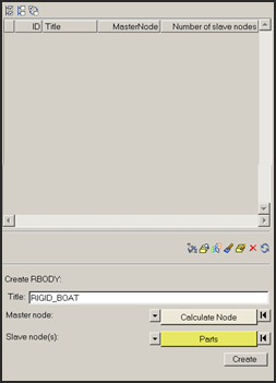
| 4. | Click Create to create the RBODY. The created RBODY appears in the table. |
| 5. | Select the created RBODY in the table and right-click and select Edit card  to open the card image panel. to open the card image panel. |
| 6. | Assign a mass of 23.04 kg to the boat. |
| 7. | Click return to return from the card image panel. |
| 8. | Click Close to close the RBODY Manager. |
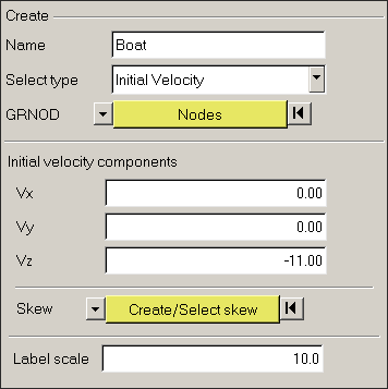
Step 10: Create Initial Velocity
| 1. | Click Tools > BCs Manager. |
| 3. | For Select type, select Initial Velocity. |
| 5. | Click the Node tab and select the master node of the RBODY created in the previous step. |
| 6. | Set Z velocity (VZ) to -11.0 indicating velocity opposite to global Z-axis. |
| 7. | Click Create to create the initial velocity boundary condition. |
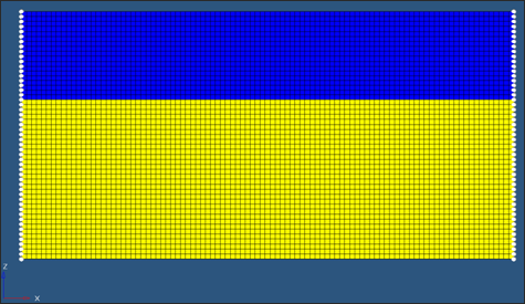
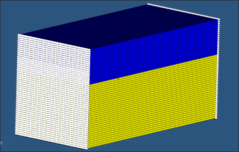
Step 11: Create Boundary Conditions on outermost faces
| 1. | In the Model browser, right-click on the Components sub-folder and select Show to display all components. |
| 2. | Enter a new boundary condition in the BCs Manager named Constraint-x. |
| 3. | For Select type, select Boundary condition. |
| 5. | Click the Node tab and select a node on both faces normal to x-axis. |
| 6. | Then click the nodes yellow tab and select By face. |
HyperMesh will automatically select nodes on the face, as shown in figure.
| 7. | Check Tx box to constraint translation in X direction. |
| 8. | Click Create to create the constraint. |
| 9. | Follow the same procedure (step 1-8) but create constraint in Y direction on the sides parallel to Y plane of global axis. |
| 10. | Follow the same procedure (step 1-8) but create constraint in Z direction on the sides parallel to Z plane of global axis. |
Step 12: Creating control cards and output requests
| 1. | Launch the HyperMesh Solver browser from View > Browsers > HyperMesh > Solver. |
| 2. | Right-click in the Solver browser general area to create the cards shown below with the given values for each parameter: |
Keyword Type
|
Keyword
|
Parameter
|
Parameter Value
|
CONTROL CARDS
|
TITLE
|
Status
|
[Checked]
|
CONTROL CARDS
|
TITLE
|
TITLE
|
Boat-Ditch-1
|
CONTROL CARDS
|
MEMORY
|
Status
|
[Checked]
|
CONTROL CARDS
|
MEMORY
|
NMOTS
|
40000
|
CONTROL CARDS
|
SPMD
|
Status
|
[Checked]
|
CONTROL CARDS
|
IOFLAG
|
Status
|
[Checked]
|
CONTROL CARDS
|
ANALY
|
Status
|
[Checked]
|
ALE-CFD-SPH
|
ALE_CFD_SPH_CARD
|
Status
|
[Checked]
|
ALE-CFD-SPH
|
ALE_CFD_SPH_CARD
|
ALE_Grid_Velocity
|
[Checked]
|
ENGINE KEYWORDS
|
RUN
|
Status
|
[Checked]
|
ENGINE KEYWORDS
|
RUN
|
RunName
|
Boat-Ditch-1
|
ENGINE KEYWORDS
|
RUN
|
Tstop
|
30.01
|
ENGINE KEYWORDS
|
PARITH
|
Status
|
[Checked]
|
ENGINE KEYWORDS
|
PARITH
|
Keyword2
|
OFF
|
ENGINE KEYWORDS
|
PRINT
|
Status
|
[Checked]
|
ENGINE KEYWORDS
|
PRINT
|
N_Print
|
-1000
|
ENGINE KEYWORDS
|
ANIM/ELEM
|
Status
|
[Checked]
|
ENGINE KEYWORDS
|
ANIM/ELEM
|
VONM
|
[Checked]
|
ENGINE KEYWORDS
|
ANIM/ELEM
|
DENS
|
[Checked]
|
ENGINE KEYWORDS
|
ANIM/ELEM
|
PRES
|
[Checked]
|
ENGINE KEYWORDS
|
ANIM/VECT
|
Status
|
[Checked]
|
ENGINE KEYWORDS
|
ANIM/VECT
|
VEL
|
[Checked]
|
ENGINE KEYWORDS
|
ANIM/VECT
|
CONT
|
[Checked]
|
ENGINE KEYWORDS
|
ANIM/DT
|
Status
|
[Checked]
|
ENGINE KEYWORDS
|
ANIM/DT
|
Tstart
|
0
|
ENGINE KEYWORDS
|
ANIM/DT
|
Tfreq
|
1.0
|
ENGINE KEYWORDS
|
DT > DT
|
Status
|
[Checked]
|
ENGINE KEYWORDS
|
DT > DT
|
Tscale
|
0.5
|
ENGINE KEYWORDS
|
DT > DT
|
Tmin
|
0.0
|
Step 13: Export the model
| 1. | Click File > Export or click the Export icon  . . |
| 2. | For File:, click the folder icon  and navigate to the destination directory where you want to export to. and navigate to the destination directory where you want to export to. |
| 3. | For name, enter boatditching_1 and click Save. |
| 4. | Click the downward-pointing arrows next to Export options to expand the panel. |
| 5. | Click Merge starter and engine file to export one solver deck (or export separately). |
| 6. | Click Export to export solver deck. |
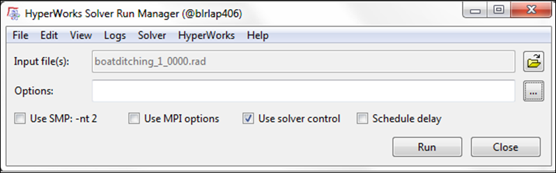
Step 14: Run the solver using RADIOSS Manager
| 1. | Go to Start > Programs > Altair HyperWorks 14.0 > RADIOSS. |
| 2. | For Input file, browse to the exercise folder and select the file boatditching_1_0000.rad. |
Step 15 (Optional): View the results in HyperView
The exercise is complete. Save your work to a HyperMesh file.
See Also:
RADIOSS Tutorials


