The slider crank model shown in the figure below consists of a rigid crank, a flexible connecting rod, and a rigid sliding block. The objective of this analysis is to determine the deformation and stress of a flexible connecting rod under the high speed motion of the system.
This tutorial includes the creation of PRBODY (rigid body definition), PFBODY (flexible body definition), and JOINT in HyperMesh 2017.
An existing finite element model is used in this tutorial.
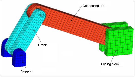
The following exercises are included:
| • | Setting up the problem in HyperMesh 2017 |
- PRBODY
- PFBODY
- JOINTS
- MBSIM (simulation parameter)
- INVELB (initial velocity)
Exercise
Step 1: Launch HyperMesh and set the OptiStruct User Profile
| 1. | Launch HyperMesh Desktop. The User Profiles dialog appears. |
| 2. | Select OptiStruct and click OK. This loads the user profile. |
Step 2: Retrieve the HyperMesh Model File
| 1. | Click on the Open Model icon  . An Open Model browser window opens. . An Open Model browser window opens. |
| 2. | Select the slider_crank.hm file you saved to your working directory from the optistruct.zip file. Refer to Accessing the Model Files. |
| 3. | Click Open. The model has five components and a few free nodes that will be used to create bodies and joints for the MBD model. |
Setting up the Problem in HyperMesh (Steps 3 - 5)
Step 3: Creating PRBodies
PRBODY is the Rigid Body Definition for Multi-body Simulation. PRBODY defines a rigid body out of a list of finite element properties, elements and grid points.
Define the parts as PRBODY (Rigid Body definition)
| 1. | From the Analysis page, enter the bodies panel. |
| 2. | Select the create subpanel using the radio buttons on the left-hand side of the panel. |
To create PRBODY for component, support.
| 3. | Click body= and enter support. |
| 4. | Click type= and select PRBODY. |
| 5. | Click props and select support. |
To create PRBODY for component, crank.
| 7. | Click body= and enter crank. |
| 8. | Click type= and select PRBODY. |
| 9. | Click props and select crank. |
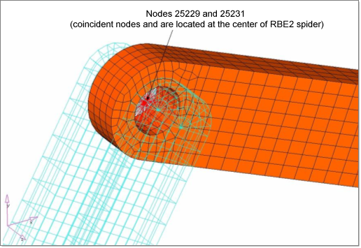
| 10. | Click nodes and select the node (ID 25231) at the center of RBE2 spider between connecting rod and crank (see the following figure). |
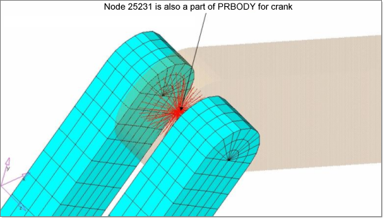
To create PRBODY for component, block.
| 12. | Click body= and enter block. |
| 13. | Click type= and select PRBODY. |
| 14. | Click props and select block. |
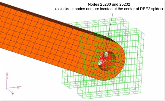
| 15. | Click nodes and select the node (ID 25232) at the center of RBE2 spider between connecting rod and block (see figure). |
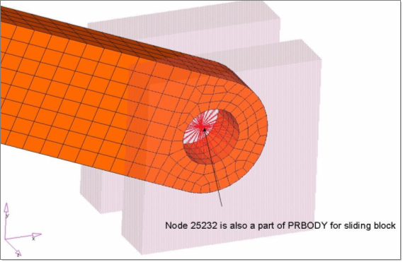
This completes the definition of PRBODY.
Step 4: Creating PFBodies
PFBODY is the Flexible Body Definition for Multi-body Simulation. PFBODY defines a flexible body out of a list of finite element properties, elements, and grid points.
Define PFBODY for the connecting rod
| 1. | Click body= and enter rod. |
| 2. | Click type= and select PFBODY. |
| 3. | Click props and select rod. |
| 4. | Click elems and select two RBE2 elements that are inside a hole on the connecting rod. |
Alternatively you could also use ‘elems by id’ and input IDs 18795 and 18796 for the two RBE2 elements.

| 5. | Select Craig-Bampton as the CMS Method: and the number of modes: set to 10. |

Step 5: Creating Joints
Here, defining all the necessary joints is required for this model. Five joints for the model are required.
Create the component for the joints
| 1. | In the Model browser, right-click and select Create > Component. |
| 2. | For Name, enter joints. |
In this tutorial three revolute joints, one fixed joint, and one translational joint are created to constrain the degrees of freedom.
Type of Joint
|
Removes
translational dof
|
Removes
rotational dof
|
Removes total
number of dof
|
Revolute
|
3
|
2
|
5
|
Fixed
|
3
|
3
|
6
|
Translational
|
2
|
3
|
5
|
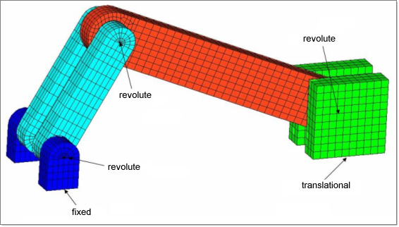
To create the joints:
| 1. | Click Mesh > Create > 1D Elements > Joints to open the Joints panel. |
First, the fixed joint between ground and support will be created.
| 2. | Click the joint type: selection switch > fixed. |
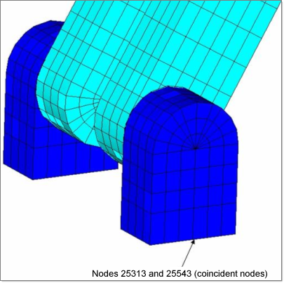
| 3. | Select node ID 25313 as first terminal (see the following figure). |
| 4. | Select node ID 25543 as second terminal. |
| Note: | Nodes 25313 and 25543 are coincident. Coincident node picking in options panel in HyperMesh will help select these coincident nodes if nodes need to be selected in the screen. |
|
Next, the revolute joint between support and crank will be created.
| 6. | Click the joint type: selection switch > revolute. |
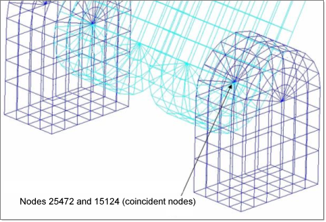
| 7. | Select node ID 25472 as a first terminal (see the following figure). |
| 8. | Select node ID 15124 as a second terminal. |
| 9. | Select coordinates as first orientation and enter x= 0.0, y= 0.0, z= 1.0. The z-axis will be the axis of rotation of revolute joint. |
A revolute joint between the crank and connecting rod will be created next.
| 11. | Click the joint type: selection switch > revolute. |
| 12. | Select node ID 25229 as a first terminal (see the following figure). |
| 13. | Select node ID 25231 as a second terminal. |
| 14. | Select the coordinates as the first orientation and enter x= 0.0, y= 0.0, z= 1.0. The z-axis will be the axis of rotation of revolute joint. |
| 15. | Click create. A revolute joint between the connecting rod and sliding block will be created next. |
| 16. | Click the joint type: selection switch > revolute. |
| 17. | Select node ID 25230 as a first terminal (see the following figure). |
| 18. | Select node ID 25232 as a second terminal. |
| 19. | Select coordinates as first orientation and enter x= 0.0, y= 0.0, z= 1.0. The z-axis will be the axis of rotation of revolute joint. |
| 20. | Click create. A translational joint between the sliding block and ground will be created next. |
| 21. | Click the joint type: selection switch > translational. |
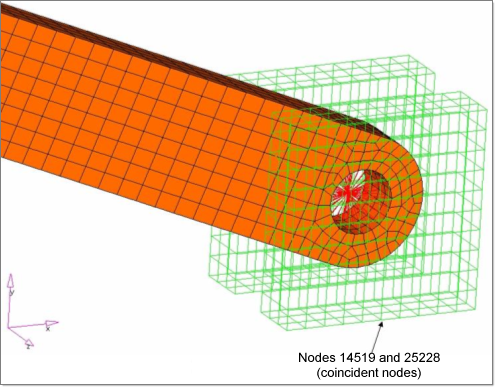
| 22. | Select node ID 14519 as a first terminal (see the figure below). |
| 23. | Select node ID 25228 as a second terminal. |
| 24. | Select coordinates as first orientation and enter x= 1.0, y= 0.0, z= 0.0. |
X is the direction of translation.
| 25. | Click create > return. |
Defining external inputs and simulation parameters (Steps 6 and 7)
The gravity force that applies to the model and MBSIM bulk data card, which is to specify the parameter for multi body simulation, will be created in this step.
Step 6: Create DTI, UNITS
| 1. | Click Setup > Create > Control Cards to open the Control Cards panel. |
| 3. | Define the unit system, as shown below. |

| 4. | Click return twice to return to the main menu. |
Step 7: Define MBSIM and INVELB
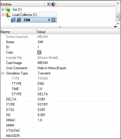
| 1. | In the Model browser, right-click and select Create > Load Collector. |
| 3. | For Card Image, select MBSIM. |
| 4. | Input the values, as illustrated below. |
| 5. | In Model browser, right-click and select Create > Load Collector. |
| 6. | For Name, enter Velocity. |
| 7. | Click Color and select any color. |
| 8. | For Card Image, select INVELB. |
| 10. | Click VX and enter -50. |
Step 8: Create an OptiStruct loadstep (also referred to as a subcase)
| 1. | Click Setup > Create > LoadSteps to open the LoadSteps panel. |
| 2. | Set the Analysis type to Multi-body dynamics. |
| 3. | For Name, enter dynamic. |
| 4. | For MBSIM, click Unspecified > Loadcol. |
| 5. | In the Select Loadcol dialog, select SIM from the list of load collectors and click OK. |
| 6. | For INVEL, click Unspecified > Loadcol. |
| 7. | In the Select Loadcol dialog, select Velocity from the list of load collectors and click OK. |
Submitting the Job
Step 9: Run OptiStruct
| 1. | From the Analysis page, enter the OptiStruct panel. |
| 2. | Click save as following the input file: field. A Save As browser window opens. |
| 3. | Select the directory where you would like to write the OptiStruct model file and enter the name for the model, slider_crank_complete.fem, in the File name: field. The .fem file name extension is suggested for OptiStruct input decks. |
The name and location of the slider_crank_complete.fem file displays in the input file: field.
| 5. | Set the memory options: toggle to memory default. |
| 6. | Set the run options: toggle to analysis. |
| 7. | Set the export options: toggle to all. |
| 8. | Click OptiStruct. This launches an OptiStruct run in a separate (DOS or UNIX) shell. |
The default files written to the directory are:
slider_crank_complete_frames.html
|
HTML report of the analysis, giving a summary of the problem formulation and the results from the final iteration.
|
slider_crank_complete.out
|
OptiStruct output file containing specific information on the file set up, estimates for the amount of RAM and disk space required for the run, and compute time information. Review this file for warnings and errors.
|
slider_crank_complete.h3d
|
Binary results file (Nodal results).
|
slider_crank_complete.stat
|
Summary of analysis process, providing CPU information for each step during analysis process.
|
slider_crank_complete_mbd.abf
|
Binary plotting file.
|
slider_crank_complete_mbd.h3d
|
Binary results file (Modal results).
|
slider_crank_complete_mbd.log
|
Log file from OS-Motion containing the information on the joints and markers, simulation etc., which are specific to MBD analysis.
|
slider_crank_complete_mbd.mrf
|
Binary results file for plotting.
|
slider_crank_complete_mbd.xml
|
Model file in .xml format – solver intermediate input deck.
|
View the Results in HyperView
This section describes how to view the results in HyperView which will be launched from within the OptiStruct panel of HyperMesh.
HyperView is a complete post-processing and visualization environment for finite element analysis (FEA), multi-body system simulation, video and engineering data.
Step 10: Review a contour plot of the displacement and stress
| 1. | While in the OptiStruct panel of the Analysis page, click HyperView. |
Note that the path and filename for slider_crank_complete.h3d appears in the fields to the right of Load model and Load results. This is fine because the .h3d format contains both model and results data.
The model and results are loaded in the current HyperView window.
| 2. | Click the Contour panel toolbar icon  . . |
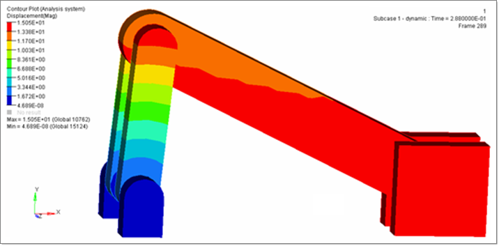
| 3. | Under Results type: select Displacement(v). |
| 5. | Verify that the Animate Mode is set to Transient  . . |
| 6. | Click the Start/Pause Animation icon to start the animation. |
| 7. | The Animation Controls are in the panel next to the playback controls. |

The HyperView playback controls
| 8. | With the animation running, use the bottom slider bar to adjust the speed of the animation. |
| 9. | Click the Start/Pause Animation icon again to stop the animation. |
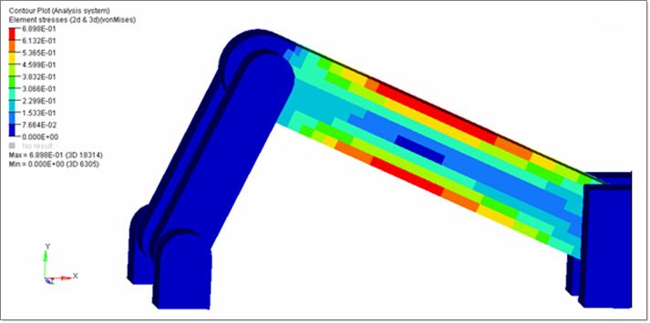
| 10. | Go to the contour panel  and select Element Stresses [2D & 3D] as Results type. and select Element Stresses [2D & 3D] as Results type. |
| 11. | Stress type should be von Mises. |
| 13. | Click the Start/Pause Animation icon to start the animation. |
See Also:
OptiStruct Tutorials


