HyperWorks Solvers

/TETRA10

/TETRA10

Previous topic Next topic Expand/collapse all hidden text  

/TETRA10

Previous topic Next topic JavaScript is required for expanding text JavaScript is required for the print function  

Block Format Keyword

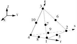
/TETRA10 - Tetrahedral Solid Elements with 10 Nodes

Description

Describes a tetrahedral solid element with 10 nodes.

Format

(1)

(2)

(3)

(4)

(5)

(6)

(7)

(8)

(9)

(10)

/TETRA10/part_ID

tetra_ID


node_ID1

node_ID2

node_ID3

node_ID4

node_ID5

node_ID6

node_ID7

node_ID8

node_ID9

node_ID10

hmtoggle_plus1Flag Definition

Field

Contents

part_ID

Part identifier of the block

(Integer, maximum 10 digits)

tetra_ID

Element identifier

(Integer)

node_ID1

Node identifier 1

(Integer)

node_ID2

Node identifier 2

(Integer)

node_ID3

Node identifier 3

(Integer)

node_ID4

Node identifier 4

(Integer)

node_ID5

Node identifier 5 (optional)

(Integer)

node_ID6

Node identifier 6 (optional)

(Integer)

node_ID7

Node identifier 7 (optional)

(Integer)

node_ID8

Node identifier 8 (optional)

(Integer)

node_ID9

Node identifier 9 (optional)

(Integer)

node_ID10

Node identifier 10 (optional)

(Integer)

clip0141

hmtoggle_plus1Comments
1.The identifier must be unique in each element family, but it is advised for each element type to have a unique element identifier in the global model.
2.The part_ID of the tetrahedral 10-node elements must be different from:
the part_ID of the brick element
the part_ID of the tetrahedral 4 node element
3.The values 1, 2 or 3 of the flag (Ismstr) for solid small strain formulation defined in /DEF_SOLID, are not compatible with the 10-node tetrahedral.
4.Elements may be degenerated: 4 to 9 nodes.
5.The 10 node tetrahedral elements are treated internally as solid elements (brick_ID), using solid materials and solid groups (grbric_ID).
6.There are two ways to define tetra 10 in interface:

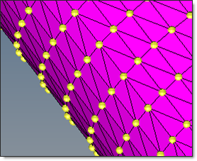
Case 1: Defined with segment (one triangle per tetra face) or with void shell3n (one void element per tetra surface).

tetra10_case1

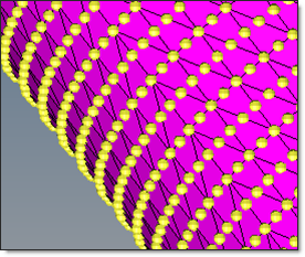
Case 2: Defined as external surface of tetra 10 (PART or GRBRICK).

tetra10_case2

Define tetra 10 ONLY in master surface:

In case 1: tetra 10 is degenerated on the surface (middle nodes are removed from tetra element).

In case 2: four triangular segments are used on each tetra face.

Define tetra 10 in master surface AND in slave surface (for this or for another interface):

In case 1: it is recommended to use only the top tetra nodes as slave nodes.

In case 2: all nodes (top and middle) have to be considered.

Define tetra 10 ONLY in slave surface (for all interfaces):

All nodes (top and middle) have to be used.

If the node group is defined in:

the master surface of an interface TYPE3, TYPE5, TYPE7 or TYPE10
or the slave surface of an interface TYPE3

and in this group some tetrahedral are the same, then it is recommended to use case 2 and define the slave node group for the interface through /GRNOD/SURF. (Because tetra 10 is degenerated on the surface within RADIOSS Starter).