Branch ID: 10
Request Number: 50000010
Description: Toe-in (Steer) and Camber
Component
|
Unit
|
Comment
|
1 (X): Left Toe-in Angle
|
deg
|
The magnitude is the global top view angle between the left wheel spindle axis and the global Y (lateral) vector. The sign is positive in toe-in and negative in toe-out. Left wheel toe-in angle is equal to the negative of the left wheel steer angle. See Figure 1 (below).
|
2 (Y): Right Toe-in Angle
|
deg
|
The magnitude is the global top view angle between the right wheel spindle axis and the global Y (lateral) vector. The sign is positive in toe-in and negative in toe-out. Right wheel toe-in is equal to the right wheel steer angle. See Figure 1 (below).
|
3 (Z): Average Toe-in Angle
|
deg
|
The mean of components 1 and 2.
|
4 (RX): Left Camber Angle
|
deg
|
The magnitude is the global front view angle between the left wheel spindle axis and the global Y (lateral) vector. The sign is positive when the bottom of the tire is inboard of the top of the tire. See Figure 2 (below).
|
5 (RY): Right Camber Angle
|
deg
|
The magnitude is the global front view angle between the right wheel spindle axis and the global Y (lateral) vector. The sign is positive when the bottom of the tire is inboard of the top of the tire. See Figure 2 (below).
|
6 (RZ): Average Camber Angle
|
deg
|
The mean of components 4 and 5.
|
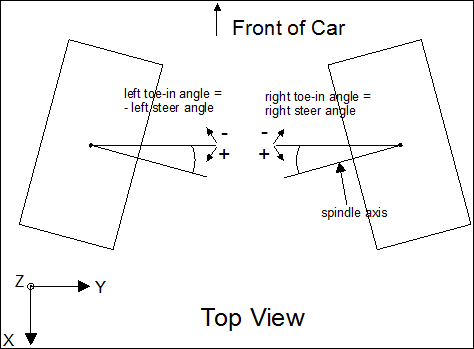
Figure 1
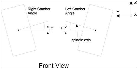
Figure 2
See Also:
List of SDF Parameter Definitions


