MotionView User's Guide

Beam

Beam

This is the first topic This is the last topic Expand/collapse all hidden text  

Beam

This is the first topic This is the last topic JavaScript is required for expanding text JavaScript is required for the print function  

This section describes the Beam entity of MotionView and shows the various usage, creation, and editing methods.

Theory/Background

Beam entity defines a straight, massless beam of uniform cross section acting between two points (Point 1 and Point 2) that belong to two different bodies (Body 1 and Body 2). The mass of the bean is lumped at Point 1 and Point 2. The stiffness properties for the beam are derived using Timoshenko beam theory.

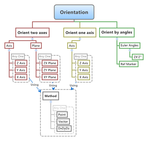
The beam axis is assumed to be along the x-axis of the Body 2 Reference Marker. The x-axis of the Body 2 Reference Marker is also defined to be the neutral axis of the un-deformed beam. The beam is assumed to undergo small rotational deflections; large rotations are not supported.

The topological information required to define an Beam is shown in the figure below:

Entity Data Members

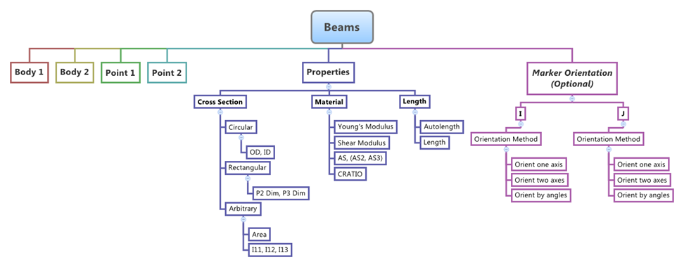
The data members of a Beam can be classified into the following members:

hmtoggle_plus1Connectivity

A Beam needs the following:

Two bodies which are connected by the Beam entity – Body 1 and Body 2
Two points that define the start and end of the Beam - Point 1 and Point2

The Beam can be modeled as a Single entity or as a Pair entity.

hmtoggle_plus1Properties

The editable properties of a Beam are:

Ratio of Displacement between Joint 1 and Joint 2
In case of User Defined properties for the Coupler:
-USER() function call statement
-Local Subroutine DLL name and path (Optional)
-USER Function Type which can be – DLL/SO, Python or MATLAB
-USER function name (Optional)
1.The Beam can have any of the three types of Cross Sections and corresponding Cross Section Properties:
a.Circular – Inner and Outer Diameters – OD and ID.
b.Rectangular – Dimensions of the two sides – P2 Dim and P3 Dim.
c.Arbitrary – Cross Section Area and the Polar Moment of Inertia of beam cross section, Second moment of Inertias along Y and Z – Area and I11, I12, I13.
2.Beam Material Properties:
a.Young’s Modulus – E.
b.Shear Modulus – G.
c.Correction Factor for Shear Deflection – AS (for Circular cross section) or AS2 and AS3 (for Rectangular and Arbitrary cross sections).
d.Elasticity Damping Ratio – CRATIO.
3.Beam Length – Autolength (automatically calculated distance between Point 1 and Point 2) or Length (user specified value).
4.If required you can also change the Marker Orientations (I and J) of the beam. This can be done using any of the three orientation methods – Orient one axis, Orient two axes, and Orient by angles.


When specifying the properties for Pair beam entities the properties can be made symmetric or can be asymmetric.

Creating and Editing Beams

To learn how to add a Beam entity to a model, please see the Constraints topic.

hmtoggle_plus1To create/add a Beam to a model:

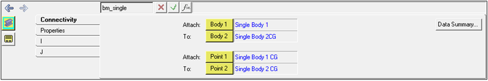
To define a beam the Connectivity and Property data have to be defined and specified.

Connectivity

1.Once a Beam has been added to the model using any of the "entity" creation methods, the panel for the Beam entity will automatically be displayed in the panel area.  See the panel examples below:

Beam Panel – Connectivity Tab – Single Entity

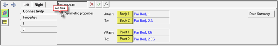
Beam Panel – Connectivity Tab – Pair Entities

2.From the Connectivity tab, click on the Body 1 collector and select the desired body from the graphics area (or double click the Body 1 collector to open the Entity selector dialog, and select the desired body).
3.In the same manner, click the Body 2 collector and pick the second body for the Beam.  
4.Pick the Point 1 and Point 2 from the Graphics area or the entity selector dialogue that pops up when you Double Click on the Point 1 or Point 2 button.

1.The default orientation for the Beam entity is such that the un-deformed beam axis is oriented along the x-axis of the Body 2 Reference Marker. The x-axis of the Body 2 Reference Marker is oriented along the axis defined by the line connecting Point 1 and Point 2 of the beam entity. This orientation can be changed using the orientation options provided on the Tabs I and J of the Beams panel.
1.Click the I tab of the Beam entity and you can change the orientation of the Beam entity Body 1 I reference marker. Refer to the Figure 4 below and steps 9 to 11 to change the orientation.
2.In the same way the Body 2 J Marker orientation can also be changed using the J tab of the Beam panel. Please note that the section properties specified will also need to be changed with respect to the changed marker orientations. Unless you have a well-defined need to change these orientations it is recommended to retain the default settings.

1.Orient two axes: you need to select two axes where one represents an axis and the other represents a plane that is parallel to the axis. The two axes can be selected using any of the three methods – Point, Vector or DxDyDz (Direction Cosines).
2.Orient one axis: you need to select one axis that represents any of the axis of Body 2 reference marker of the Beam entity. The other two axes are defined automatically using the Left Hand Rule. The axis can be selected using any of the three methods – Point, Vector or DxDyDz (Direction Cosines).
3.Orient by angles: if you know the orientation of the Beam in terms of the Euler Angles (ZX’Z’’), the same can be used to define the orientation of the Beam. A Ref Marker can be specified as reference for the Angle Values. The default is Global Frame.  


â Note:

When defining a Pair Beam Entities use pair entities for Body 1, Body 2, Point 1, Point 2 etc. The same steps as shown above can be used to define Pair Beam entities too.


Properties


The Properties of a Beam entity are:


4.Cross Section
5.Material
6.Length


Define Properties


7.After the connectivity options are all defined click the Properties Tab for the beam.
8.The Tab will be displayed as shown in the Figure 5 below.


Circular Cross Section


Figure 5: Properties Tab – Circular Beams


9.To define a Beam with Circular cross section, select Circular from the Type: pull down menu. See Figure 5 above.
10.Enter the values for the Young’s Modulus (E) and Shear Modulus (G) in the corresponding fields.
11.Enter the values of the Outer (OD) and Inner Diameters (ID) of the circular beam, to define a Solid beam leave the ID value unchanged or 0.0.
12.Enter the value for the Shear Deflection Correction Factor (AS).
13.Enter the value for Damping Factor (CRATIO).
14.The length of the beam is automatically calculated if it is set to Autolength, to change the same click the Length pull down menu and select Length and enter a value for the desired length of the Beam.


Rectangular Cross Section


Figure 6: Properties Tab – Rectangular Beam


15.To define a Beam with Rectangular cross section, select Rectangular from the Type: pull down menu. See Figure 6 above.
16.Enter the values for the Young’s Modulus (E) and Shear Modulus (G) in the corresponding fields.
17.The Rectangular cross section will have two perpendicular sides along two axes perpendicular to the axis of the beam. Enter the dimensional values of two sides in the fields for P2 Dim: and P3 Dim:.
18.Enter the value for the Shear Deflection Correction Factor in the directions of the P2 Dim and P3 Dim respectively in the fields AS2: and AS3:.
19.Enter the value for Damping Factor (CRATIO).
20.The length of the beam is automatically calculated if it is set to Autolength, to change the same click the Length pull down menu and select Length and enter a value for the desired length of the Beam.


Arbitrary Cross Section


Figure 7: Properties Tab – Arbitrary Cross Section Beam


21.To define a Beam with Arbitrary cross section, select Arbitrary from the Type: pull down menu. See Figure 7 above.
22.Enter the values for the Young’s Modulus (E) and Shear Modulus (G) in the corresponding fields.
23.Enter the value for the Cross Sectional Area in the Area: field.
24.Enter the value of the Polar Moment of Inertia of the beam cross section in the field for I11:.
25.Enter the values of the Second Moment of Inertia of the beam along the Y and Z axis of the beam (Axes Perpendicular to the Beam Axis) in the fields for I22: and I33:.  
26.Enter the value for the Shear Deflection Correction Factor in the directions of Y axis and Z axis of the beam (Axes Perpendicular to the Beam Axis) respectively in the fields AS2: and AS3:.
27.Enter the value for Damping Factor (CRATIO).
28.The length of the beam is automatically calculated if it is set to Autolength, to change the same click the Length pull down menu and select Length and enter a value for the desired length of the Beam.
29.When specifying the properties for Pair Beam entities, there is an option to make those properties Symmetric. Click the appropriate Symmetric check box (on the Connectivity Tab, see Figure 3 above) to enable the same.
30.The same steps apply when defining the properties of Pair Beam Entities too.
22.When defining a Pair Coupler, use pair entities for Joint 1Joint 2, etc. 

Note - The same steps as shown above can also be used to define Pair Coupler entities.

hmtoggle_plus1To edit or change the definition of a Coupler entity:
1.Left click the Couplers panel icon entityCouplers-24 on the Constraint toolbar.

The Project Browser will filter the entities and display only the Couplers in the model.

2.Select the desired coupler entity in the Project Browser.

The corresponding panel is automatically displayed.

3.From the Connectivity tab, use the Coupler type drop-down menu to change the coupler type, or use the collectors to change the joints and other attributes.

Beam in MDL and XML Formats

The model containing the Beam can be saved in MDL format from MotionView and exported in the MotionSolve XML format.

hmtoggle_plus1Beam in MDL (Model Definition Language)

A Beam entity can be completely defined in MDL format using the following statements:


*Beam()
*SetBeam()
*BeamPair()


These Beams can further be Single or Pair. Let us look at some examples below.


The Beam entity is defined using a *Beam statement and the properties of the beam are defined using *SetBeam statement.

All of the types of entities mentioned above can be added to the model using the MDL Statements shown below:

Syntax:

*Beam(beam_name, "beam_label", body_1,

                              body_2,

                              point_1,

                              point_2)

Example:

*Beam( bm_single, "Single Beam Circular", b_sb1, b_sinb2, p_sbcg, p_sinb2cg )

Syntax:

*SetCoupler(coupler_name, USER, `expr`)

Example:

*SetCoupler( c_jcoup, USER, `USER(10,25)` )


*SetLocalUserDLLFlag( c_jcoup, true )

*SetLocalUserFunction( c_jcoup, "COUSUB", DLL )

*SetLocalUserDLL( c_jcoup, "C:/Models/COUSUB.dll" )

Syntax:

*CouplerPair(coupler_name, "coupler_label",  2JOINT|3JOINT

                                            joint_1,

                                            joint_2,

                                            [joint_3]

                                            TRANS|ROT,

                                            TRANS|ROT,

                                            [TRANS|ROT])

Example:

*CouplerPair( c_coup_pair, "Coupler Pair", 3JOINT, j_0, j_1, j_2, ROT, ROT, ROT )

*SetCoupler( c_coup_pair, LEFT, 4, 3.2 )

Syntax:

*SetCoupler(coupler_name,  , ratio_l, ratio_r)

Example:

*SetCoupler( c_coup_pair,              , 4, 3.2, 4, 3.2 )

Syntax:


*SetCoupler(coupler_name, , USER, `expr`, `expr` )


Example:

*SetCoupler( c_coup_pair2, , USER, `USER(301001, 301003, 25)`, `USER(301002, 301005, 25)` )


*SetLocalUserDLLFlag( c_coup_pair2.l, true )

*SetLocalUserDLL( c_coup_pair2.l, "C:/Models/COUSUB.dll" )

*SetLocalUserFunction( c_coup_pair2.l, COUSUB, DLL )


*SetLocalUserDLLFlag( c_coup_pair2.r, true )

*SetLocalUserDLL( c_coup_pair2.r, "C:/Models/COUSUB.dll" )

*SetLocalUserFunction( c_coup_pair2.r, COUSUB, DLL )

Please refer to the *Coupler, *CouplerPair, *SetCoupler, and *SetCouplerPair topics for a detailed description of each MDL statement.

Note: To learn how to create a complete model using MDL statements, please refer to tutorial MV-1060: Introduction to MDL.

hmtoggle_plus1Coupler in XML Format

The Coupler when exported to the MotionSolve XML format is defined as a Constraint_Coupler statement.

Syntax:

<Constraint_Coupler

   id                     = "integer"

   label                  = "Coupler Entity Label"

   joint1_id              = "integer"

   freedom_1              = { "T" | "R" }

   joint2_id              = "integer"

   freedom_2              = { "T" | "R" }

[

   joint3_id              = "integer"

   freedom_3              = { "T" | "R" }

]

{

      coefficients        = "double, double [, double]"

   |

      usrsub_dll_name     = "valid_path_name"

      usrsub_param_string = "USER( [[par_1][, ...][, par_n]] )"

      usrsub_fnc_name     = "custom_fnc_name" >

   |

      script_name       = valid_path_name

      interpreter         = "PYTHON" | "MATLAB"

      usrsub_param_string = "USER( [[par_1 [, ...][,par_n]] )"

      usrsub_fnc_name        = "custom_fnc_name" >

}

</Constraint_Coupler>

In case of a three joint Coupler with linear properties the model statement will be as shown below:

<Constraint_Coupler

  id                  = "301002"

  label               = "Three Joint Coupler"

  joint1_id           = "301003"

  freedom_1           = "R"

  joint2_id           = "301004"

  freedom_2           = "R"

  joint3_id           = "301005"

  freedom_3           = "R"

  coefficients        = "1. 1. 1.5"

/>

In case of a three joint Coupler with User-defined properties, the model statement will be as shown below:

<Constraint_Coupler

  id                  = "101004"

  label               = "Coupler Pair User-left"

  joint1_id           = "101006"

  freedom_1           = "R"

  joint2_id           = "101007"

  freedom_2           = "R"

  joint3_id           = "101008"

  freedom_3           = "R"

  usrsub_param_string = "USER(301001,301003,25)"

  usrsub_dll_name     = "C:/Models/COUSUB.dll"

  usrsub_der1_name    = "COUXX"

  usrsub_der2_name    = "COUXX2"

/>

To understand the complete syntax of the Constraint_JPRIM XML model statement, please refer to the MotionSolve Reference Guide Page for Constraint_Coupler.

Creating and Editing Couplers using Tcl

In MotionView, Tcl can be used to add any MDL entities to the model. There are two TCL commands that can be used to add an entity:

hmtoggle_arrow1InterpretEntity

Syntax:

mdlmodel_handle InterpretEntity new_handle keyword varname label

In case of the Coupler the statement will look as shown below:

mdlmodel_handle InterpretEntity joint Coupler c_jcoup "\"Two Joint Coupler\"" 2JOINT j_transjt j_RevJt "TRANS" "ROT" ;

hmtoggle_arrow1InterpretSet

Syntax: 

mdlmodel_handle InterpretSet keyword tokens;

In case of the Coupler the statement will look as shown below:

mdlmodel_handle InterpretSet SetCoupler c_jcoup -0.9;

The command InterpretEntity is used to add entities to the model and the command InterpretSet is used to set the entity properties.  So in the case of the Coupler, the properties that can be set are the Joint Initial Conditions. Extended definitions for InterpretEntity and InterpretSet can be found in the HyperWorks Desktop Reference Guide.

Note - When using the InterpretEntity and InterpretSet commands, it is important to also use the Evaluate command in order for the changes to take effect immediately.

To learn how to create a complete model using Tcl commands, please refer to tutorial MV-1040: Model Building Using Tcl.

Example Models

The following example files are available:

hmtoggle_plus1Coupler.mdl

The example below shows a Coupler connecting two bodies:


See Also:

Coupler Panel

Adding Removing Entities

*Coupler (MDL Model Statement)

*CouplerPair (MDL Model Statement)

*SetCoupler (MDL Model Statement)

Constraint_Coupler (XML Command)

mdlIObject InterpretEntity (Tcl Command)

mdlIObject InterpretSet (Tcl Command)