In this tutorial, you will learn how to create a sequential simulation script to simulate the extension and retraction of the landing gear.
Sequential Simulation
Often, the total dynamic behavior of a multi-body model needs to be captured through more than one solution sequence. Typical examples include:
| 1. | The model configuration changes after a certain amount of time. |
| 2. | One type of analysis has to occur before the other. For example, a static solution is required before a dynamic run. |
| 3. | Complex models may not solve with a single solver setting. The solver settings may need to be changed for a certain period in the overall simulation time. |
Such conditions may be simulated by providing a set of commands to the solver that achieves the above type of sequences. Such simulations are referred to as sequential simulations. Generally, the solver receives more than one solution (simulate) command. You’ll learn to script such a simulation sequence through this exercise.
Exercise
In this exercise, a landing gear mechanism is simulated for its extension and retraction. A sequence of simulations need to be scripted such that the mechanism is retracted within a certain period of time at which the simulation is halted, the model configuration is changed for retraction and the solution is executed again for extension.
Main Landing gear of an aircraft
| Note | Copy the files MainLandingGear.mdl, Aircraft_Structure.hm and MainLandingGear.h3d, located in the mbd_modeling\interactive\aero folder, to your <Working directory>. |
Phase 1
In this phase, you will prepare the landing gear model to simulate the retraction of the landing gear.
Step 1: Opening the landing gear mechanism.
In this step, you will open a landing gear model and attach a graphic for the aircraft body.
| 1. | From the Model-Main toolbar, click the Open Model icon,  . . |
Or
Open model by selecting File > Open > Model.
| 2. | From the Open model dialog, select the file MainLandingGear.mdl and click Open. |
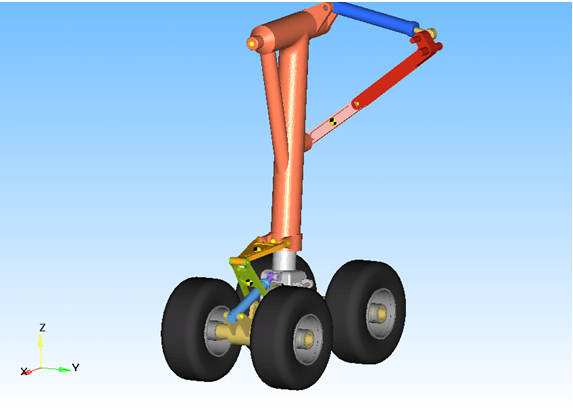
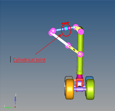
Once the model is loaded it will look as it does below. Review the model for its bodies and joints.
The model consists of linkages of the cylinder and piston that hold the wheel as well as linkages for the extension and retraction of the whole landing gear unit within the aircraft body. The model also contains a body defined for aircraft but without graphics. As a first step, you’ll add a graphic for the aircraft body part for visual representation.
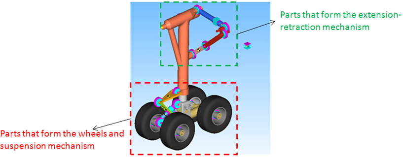
Main landing gear mechanism
Use a HyperMesh file to create a graphic for the aircraft body.
| 3. | From the Tools menu, select the Import CAD or FE utility. |
| 4. | Select the option Import CAD or Finite Element Model Only. With this selection, only the graphics will be imported without creating any bodies. |
| 5. | For Input File, select HyperMesh. For Output File, select H3D. |
| 6. | Click the Input File file browser icon,  , and select the HyperMesh file Aircraft_Structure.hm as the input file. , and select the HyperMesh file Aircraft_Structure.hm as the input file. |
| 7. | Save the file as Aircraft_Structure.H3D in the working directory. |
| 9. | When the H3D file is generated and the graphic is imported, the import success message is displayed. Click OK. |
| 10. | Click the Graphics icon  in the MotionView toolbar. in the MotionView toolbar. |
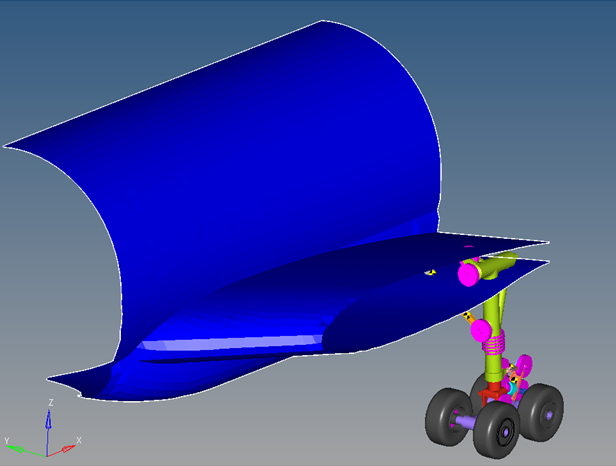
The model after importing a graphic for the aircraft body.
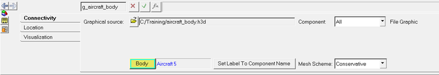
| 11. | Select the just-added graphic from the Graphic area. The panel for the aircraft body is displayed |
| 12. | From the Connectivity tab |
| - | Resolve the Body collector to Aircraft 5. |
| - | The H3D file has only one component, (aircraft_body), so the Component list can be set to All or use the drop-down menu to select the the sole component. |
Step 2: Defining a motion to retract the landing gear.
In this step, define the motion to retract the landing gear.
| 1. | From the Project Browser, right-click on Model and select Add Constraint > Motions (or right-click the Motions icon,  , from the toolbar). Add a motion with Label as Retraction Motion and Varname as mot_ret. Resolve the Joint to the Cylindrical Joint ActPis_ActCyl_Cyl (shown in the image below), which is defined between the bodies Activating Cylinder and Activating Piston. , from the toolbar). Add a motion with Label as Retraction Motion and Varname as mot_ret. Resolve the Joint to the Cylindrical Joint ActPis_ActCyl_Cyl (shown in the image below), which is defined between the bodies Activating Cylinder and Activating Piston. |
Rev joint
| 2. | From the Motion panel > Properties tab, under Define by, select Expression. In the Expression field, enter the expression `STEP(TIME,0,0,5,-750)`. |
| Note | The above STEP expression ramps the value of motion from 0 at 0 second to -750 at 5 seconds. For more information on this solver function available within MotionSolve, please refer the MotionSolve on-line help. |
| 3. | Add another motion and name it Aligning_Motion. Resolve the Joint to the Cylinderical Joint LnkCyl_LnkPis_Cyl defined between the MLG Cyl and MLG Pis bodies (see the image below). |
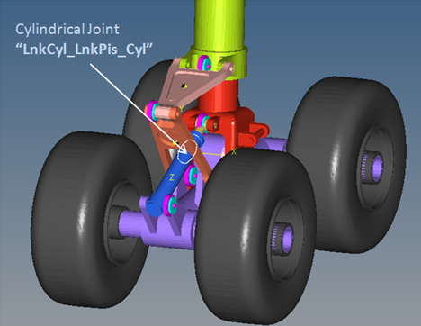
Translation joint
| 4. | From the Properties tab of the panel, under Define by, select Expression. In the Expression field, enter the expression `STEP(TIME,0,0,2,-100)`. |
| 5. | Save your model as landinggear_motion.mdl. |
Step 3: Running a dynamic analysis to simulate the retraction of the main landing gear.
In this step, run a transient analysis of the main landing gear mechanism.
| 1. | In the Run panel, set the End time to 5 seconds. |
| 2. | Click the Save and run current model browser button and enter the name for the run file as lg_retract.xml. Click Save. |
| 3. | Click Run. Once the simulation is completed, close the solver window and the Message Log. |
| 4. | From the Run panel, review the results animation by clicking on Animate button. |
Phase 2
In this phase, write a Templex template to script and run a sequential simulation to simulate the retraction and extension of the landing gear mechanism.
Step 1: Defining an extension motion for the landing gear.
In this step, model the extension motion of the landing gear.
| 1. | From the Project Browser, right-click Model and select Add Constraint > Motions (or right-click the Motions icon, , from the toolbar). Add another motion with Label as Extension Motion and Variable Name as mot_ext. Resolve the motion to the same joint for which the Retraction Motion has been defined. |
| 2. | From the Properties tab, set the type of motion as Expression and enter the following in the Expression field: `STEP(TIME,5,-750,10,0) `. |
Step 2: Defining a template to run the sequential simulation.
In this step, write a template to script a sequential simulation.
| 1. | From the Project Browser, right-click on Model and select Add > General MDL Entity > Template (or right-click the Template icon,  , from the toolbar). Specify a Label and Varname and click OK. , from the toolbar). Specify a Label and Varname and click OK. |
| 2. | For Type, select Write text to solver command file. |
| 3. | Enter the script given below. The entries in the curly braces {}, refer to the idstring of either Extension Motion or Retraction Motion. These idstring attribute can also be accessed using the Expression builder,  . . |
| Note | The following commands are MotionSolve command statements in the XML format. Since the solver refers to entities through their ID numbers, the element_id value is resolved to the motion IDs. If you have used different varnames for the motions than mentioned below, the text could differ. |
<!—-Deactivate the extension motion first -->
<Deactivate
element_type = "MOTION"
element_id = "{MODEL.mot_ext.idstring}"
/>
<!—-Simulate for 5 seconds -->
<Simulate
analysis_type = "Transient"
end_time = "5.0"
print_interval = "0.01"
/>
<!—-Deactivate the retraction motion -->
<Deactivate
element_type = "MOTION"
element_id = "{MODEL.mot_ret.idstring}"
/>
<!—-Activate the extension motion that was deactivated during the first simulation -->
<Activate
element_type = "MOTION"
element_id = "{MODEL.mot_ext.idstring}"
/>
<!—-Simulate for 5 more seconds -->
<Simulate
analysis_type = "Transient"
end_time = "10.0"
print_interval = "0.01"
/>
| <STOP/> | <!—- Stop the simulation. Any further commands below this command will not be executed --> |
The above script has five blocks.
Block 1 – Deactivates the motion which defines the extension of the landing gear.
Block 2 – Simulates the model for the retraction of the landing gear.
Block 3 – Deactivates the motion used to retract the landing gear
Block 4 – Activates the motion which defines the extension of the landing gear.
Block 5 – Simulates the model for the extension of the landing gear.
The Stop command is used to stop the simulation at the time set in the last Simulate block.
| Note | A template can be used either to add modeling entities to the solver deck, such as joints, markers, and so on, that may not be supported by MotionView, or command entities such as simulation parameters, activation and deactivation, and so on. The MotionSolve XML is divided into two sections. |
| 1. | Model section: All model elements are defined. To write to this section from the template, for Type select Write text to Solver input deck. |
| 2. | Command section: Commands for the solver simulation are defined. To write to this section from the template, for Type select Write text to Solver command file. |
Step 3: Simulating and animating the model.
In this step, run the model to simulate the retraction and extension of the main landing gear model and animate it.
| 1. | From the Run panel, specify the filename as MLG_Simulation.xml and click Run. |
| 2. | Once the solution is complete, close the HyperWorks Solver View window. |
| 3. | Click the Animate button and review the animation. |
Phase 3
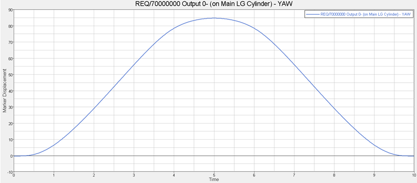
In this phase, you will create output requests and re-run the model to measure the Angular Displacement and Angular Velocity of the landing gear.
| 1. | From the Project Browser, right-click on Model and select Add > General MDL Entity > Outputs (or right-click the Outputs icon,  , from the toolbar). , from the toolbar). |
| 2. | Create an output request. From the Outputs panel: |
| - | Set Type to Displacement and Entity. |
| - | Use the drop-down menu to select the Joint collector. |
| - | For the Joint, select the Revolute Joint between the Main LG Cylinder and Aircraft-5, MLG_Ac_Rev. |
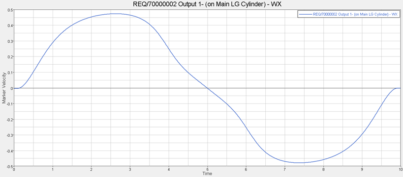
| 3. | Create another output request to measure the velocity at the same joint as above. |
| 4. | Re-run the analysis with these output requests and plot the requested results from the generated PLT file in HyperGraph. |
| 5. | Save your model and exit your HyperWorks session. |


