|
»Click here to display Table of Contents«
|

Front SLA (2pc LCA) |

|

|

|

|
|
Front SLA (2pc LCA) |
|
|
|

|
|
»Click here to display Table of Contents«
|
Front SLA (2pc LCA) |
|
|
|
|
|
Front SLA (2pc LCA) |
|
|
|
|
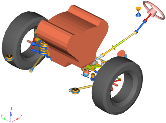
A “Short-Long Arm” or SLA suspension is included in the Vehicle Library. This configuration is also known as a “Double Wishbone” suspension. The SLA name is derived from the length of the control arms. The lower arm is typically long to provide a good spring lever ratio. The upper arm is typically short to provide the proper camber curve. This suspension is widely used on cars, light trucks, and on independent suspension heavy trucks. The two (2) piece lower control arm is the only difference between the two front SLA suspensions.
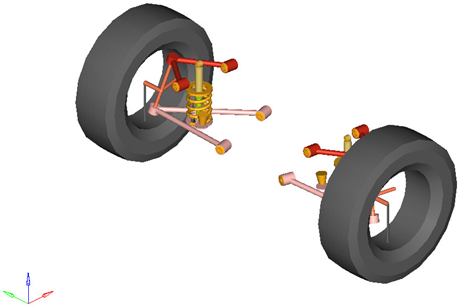
Front SLA Suspension with Two (2) Piece Lower Control Arm and Optional Coil Spring, Shock Absorber, and External Jounce Bumper Subsystems
In conventional designs the coil spring (or optionally a torsion bar), shock absorber, and jounce bumper act between the lower control arm and chassis. The lower control arm carries most of the load and defines the motion of the lower ball joint location on the knuckle. The Upper control arm carries smaller loads and defines the motion of the upper ball joint location on the knuckle. The steering motion of the knuckle is controlled by the tie rod and the motion of the steering system. In the Vehicle Library the steering systems contain the tie rod.
The SLA suspension with two (2) piece lower control arm offers a standard set of attachments, options, and properties that you can set by selecting the suspension system in the Project Browser to display the System/Assembly panel.
Attachments determine how the system attaches to the rest of the model. The SLA suspension with two (2) piece lower control arm includes attachments for the lower control arm (LCA), upper control arm (UCA), and the tension strut:
| • | The lower control arm attaches to the sub-frame by default. When a sub-frame is not present in the model, the Assembly Wizard attaches the lower control arm to the vehicle body. If the vehicle body is not present, for example in a half vehicle model, then the Assembly Wizard will attach the lower control arm (LCA) to ground. You can set the attachment for the lower control arm using the Attachments Wizard or by selecting the SLA suspension system in the Project Browser and revising the attachments within the Attachments tab on the System/Assembly panel. |
| • | The upper control arm (UCA) attaches to the vehicle body by default. When a vehicle body is not present, the Assembly Wizard attaches the UCA to ground. You can set the UCA attachment as you desire using the Attachment Wizard or by selecting the SLA suspension in the Project Browser and revising the attachments within the Attachments tab on the System/Assembly panel. |
| • | The tension strut attaches to the sub-frame by default. When a sub-frame is not present in the model, the Assembly Wizard attaches the lower control arm to the vehicle body. If the vehicle body is not present, for example in a half vehicle model, then the Assembly Wizard will attach the tension strut to ground. |
The SLA suspension system with two (2) piece lower control arm includes a Compliant option. When the SLA suspension’s Compliant option is set to No, the upper control arm bushings are replaced with revolute joints. The upper control arm bushings are replaced with a single revolute joint located at the forward bushing, with a rotational axis directed along the line from the forward bushing to the rear-ward bushing.
The SLA suspension system with two (2) piece lower control arm includes a Spindle compliance option. When the Spindle compliance option is set to Yes, the wheel body connects to the wheel hub via universal joint and bushing. The universal joint allows camber and toe deflection of the wheel relative to the wheel hub. The wheel hub bushing’s Kx and Ky rates determine the amount of spindle compliance introduced.
The SLA suspension system with two (2) piece lower control arm includes a static alignment dataset and form holding toe and camber variables that determine the orientation of the wheel relative to the knuckle and body in the Global coordinate system. The toe and camber variable values control the location of the spindle align point relative to the wheel center point through parametric expressions. You can view these expressions by selecting the spindle align point and examining its X, Y, and Z locations.
To set the values for toe and camber, select either the static alignment dataset or form and alter the values of the toe and camber variables. It is important to note that the left and right wheels’ toe and camber values must be symmetric. You cannot set the toe and camber angles independently for the two wheels.
Depending on your needs, you can use the Assembly Wizard to select whether your SLA suspension includes stabilizer bar, spring, shock-absorber, jounce bumper, or rebound bumper subsystems. You can also select between different types of subsystems, like coil springs and torsion bar springs. In addition you can select how the subsystem acts, for example whether the rebound bumper is internal to the shock absorber or external.
When you finish creating your model using the assembly wizard the subsystems you have chosen to add to your SLA suspension show in the browser as child of the SLA suspension. The table below shows the optional subsystems available with the SLA suspension:
Subsystem |
Options |
Stabilizer Bar |
None |
Stabilizer Bar with Links |
Two (2) Piece Bar with Links |
Spring |
None |
Coil Springs |
Torsion Springs |
Shock Absorber |
None |
Two (2) Inline Joints |
One (1) Cylindrical Joint |
Jounce Bumper |
None |
Internal to Shock |
External Jounce Bumper |
Rebound Bumper |
None |
Internal to Shock |
External Rebound Bumper |
| • | Coil springs act between the lower control arms (LCA) and the vehicle body. |
| • | The SLA suspension system contains points for the upper and lower spring seats to locate coil springs. |
| • | Torsion springs act between the lower control arms (LCA) and the vehicle body. The torsion spring subsystem contains points for locating the torsion bar attachment to the lower control arm and to the vehicle body. When a torsion spring is used, the upper and lower spring seat points in the SLA suspension are not used. |
| • | Internal jounce and rebound bumpers act between the shock absorber piston and tube. |
| • | External jounce and rebound bumpers act between the lower control arm and the Vehicle Body. |
| • | Suspensions created without a spring or a shock absorber subsystem will not function in a full vehicle analysis. |
| • | You can alter how optional subsystems attach to the suspension by selecting the subsystem in the Project Browser and altering the subsystem’s attachments. |
Points locate the joints and bushings that connect the suspension bodies to one another. The image below shows the principal points for the SLA suspension with a two piece lower control arm:
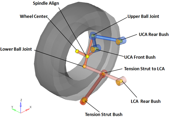
Right Side Principal Points – Front SLA Suspension with Two (2) Piece Lower Control Arm
| Note | The image above omits the left side of the suspension, points locating body centers of mass, and points that locate the optional subsystems (springs, dampers, bump stops and stabilizer bar) for clarity. |
The SLA suspension with two (2) piece lower control arm is comprised of the bodies shown in the image below:
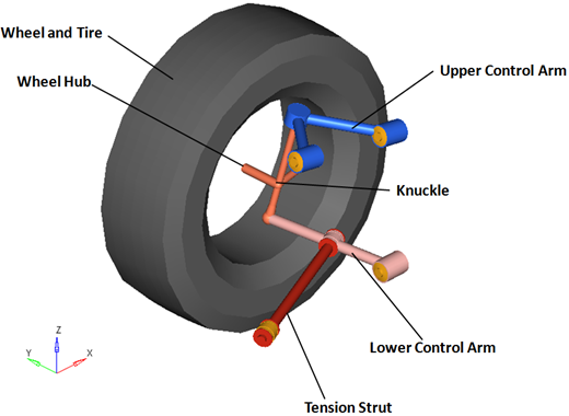
Right Side Bodies – Front SLA Suspension with Two (2) Piece Lower Control Arm
| Note | The wheel hub body has no associated graphics and therefore is not visible in the image above. |
Optional subsystems may add bodies to the suspension, for example the shock absorber adds two bodies: a shock rod and shock tube. Any bodies added by optional subsystems have been omitted from the image above for clarity.
The table below describes the bodies, bushings, and joints for the front SLA suspension with a two (2) piece lower control arm (LCA):
| Note | The table omits the left side joints for clarity. |
Label |
Type |
Body 1 |
Body 2 |
Point |
Notes |
|---|---|---|---|---|---|
Lower Ball Joint |
Spherical |
Knuckle |
Lower Control Arm |
Lower Ball Joint |
---- |
Upper Ball Joint |
Spherical |
Knuckle |
Upper Control Arm |
Upper Ball Joint |
---- |
Wheel Spindle |
Revolute |
Wheel Hub |
Knuckle |
Wheel Center |
---- |
Wheel Hub |
Fixed-Joint |
Wheel |
Wheel Hub |
Wheel Center |
When the Spindle compliance is set to Yes, the joint type changes to universal. |
Tension Strut Bush |
Universal |
Tension Strut |
Subframe, Vehicle Body or Ground |
Tension Strut Bush |
When the Compliant option is set to No, the compliance for this joint is turned "Off" and behaves as a pure universal joint. |
LCA Bushing |
Bushing |
Lower Control Arm |
Subframe, Vehicle Body or Ground |
LCA Rear Bush |
When the Compliant option is set to No, the compliance for this joint is turned "Off" and behaves as a pure universal joint. |
UCA Front Bush |
Bushing |
Upper Control Arm |
Upper Control Arm |
UCA Front Bush |
When the Compliant option is set to No, the bushing becomes a revolute joint. |
UCA Rear Bush |
Bushing |
Upper Control Arm |
Subframe, Vehicle Body or Ground |
UCA Rear Bush |
When the Compliant option is set to No, this bushing is deactivated |
The following image shows the location of the joints and bushings in the suspension:
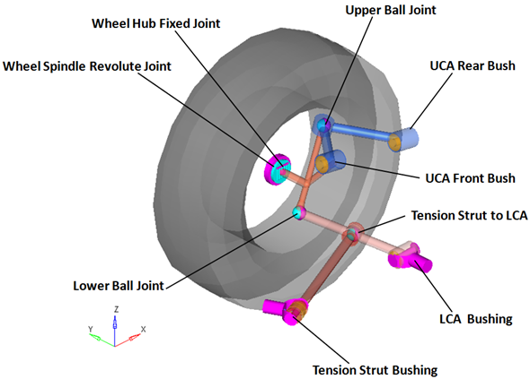
Right Side Joints and Bushings: SLA Suspension with Two (2) Piece Lower Control Arm
The SLA system can be used in either a half car or a full vehicle analysis. The default geometry and mass is that of a passenger car or light truck, however the model and data can be revised to reflect any size vehicle, from a large truck to a scale model car.
| • | The wheel body represents the mass and inertia of the tire and the rim. |
| • | The wheel hub body represents the mass and inertia of other rotating bodies such as a brake rotor, but not the half-shafts if the suspension is driven. The wheel hub and brake rotor have no associated graphics. |
| • | The wheel and wheel hub parts use the Wheel CG location as the center of gravity. |
| • | The upper control arm bushings are defined so their axes are parallel. If the front bushing is moved, both the front and rear bushing realign so they have the same axis of rotation. The lower control arm bushings’ rotational axes are defined in the same manner. |
| • | When the suspension is switched from Compliant to Kinematic (via the Option menu on the System/Assembly panel in MotionView) the upper control arm bushings are replaced with a single revolute joint located at the forward bushing, with a rotational axis directed along the line from the forward bushing to the rear-ward bushing. The lower control arm bushings are replaced with a revolute joint in the same fashion. |
| • | Each body’s Center of Gravity (CG) is estimated from the body’s geometry. The formulas are coded into the point panel and can be seen using the graphical user interface. If more accurate CG locations are available they should be used. |
| • | The point giving the location of the ball joint between the suspension knuckle and steering tie rod point (Outer Tie Rod Ball) resides in the steering system. |
| • | A wide variety of combinations of suspensions and subsystems can be built using the Assembly Wizard. You are encouraged to build systems and understand the resulting model using the graphical user interface. |
| • | When building a new suspension model, build the model with all of the optional systems (stabilizer bar, etc.) included in the model. Immediately turn off the systems using the Project Browser and run an analysis on the base suspension to ensure it solves properly. As data becomes available for the optional systems; activate those systems and populate them with data. |
Front-Half-Vehicle Model Employing a SLA Suspension with a Two (2) Piece Lower Control Arm
The image below shows the MotionView Project Browser view of the systems in a fully populated front suspension model. The Frnt SLA susp (2 pc LCA) system has five “child” systems.
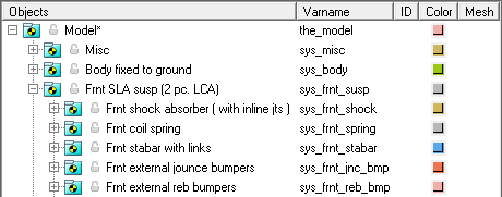
Browser view of a Front-Half-Vehicle Model Systems and Subsystems Employing a SLA Suspension with Two (2) Piece Lower Control Arm
| • | Front SLA (1pc LCA) |
| • | Rear SLA (1pc LCA) |
| • | Rear SLA (2pc LCA) |