|
»Click here to display Table of Contents«
|

Rear Linked Solid Axle |

|

|

|

|
|
Rear Linked Solid Axle |
|
|
|

|
|
»Click here to display Table of Contents«
|
Rear Linked Solid Axle |
|
|
|
|
|
Rear Linked Solid Axle |
|
|
|
|
A Rear Linked Solid Axle suspension is included in the Vehicle Library. The Rear linked solid axle is a dependent suspension (the wheels are connected via a solid beam) which is commonly found in off-road vehicles, SUVs, and rear wheel drive vehicles. This suspension is known for its simplicity and low cost. A differential is included when it is a driven axle. Including the track bar (which is used to restrain the lateral movement of the axle) will make this an asymmetric suspension.
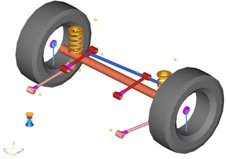
Rear Linked Solid Axle Suspension
| • | The wheel is connected to the wheel hub with a fixed joint. |
| • | The wheel hub is connected to the axle with a revolute joint. |
| • | The axle is connected to the lower and upper links with bushings. |
| • | The upper links and lower links are connected to a sub frame or the chassis with two bushings. |
| • | One end of the track bar is connected to the axle with a bushing, while the other end is connected to the vehicle body with another bushing. |
| • | All links are modeled as rigid bodies. |
| • | This suspension is asymmetric due to the track bar anchor locations. |
When you finish creating your model using the Assembly Wizard, the subsystems you have chosen show in the Project Browser as children of the Rear linked solid axle suspension. The table below shows the optional subsystems available with the Rear linked solid axle suspension:
Subsystem |
Options |
Stabilizer Bar |
None |
Multiple Beam |
Two (2) Piece Beam |
Spring |
None |
Coil Spring |
---- |
Shock Absorber |
None |
Inline Joints |
Cylindrical Joints |
Engine |
None |
Longitudinal |
---- |
Jounce Bumper |
None |
Internal to Shock |
External to Shock |
Rebound Bumper |
None |
Internal to Shock |
External to Shock |
Sub-frame |
None |
On |
Off |
The Vehicle Library has a large number of default connections and logic built into the library. These connections are easily changed using the MotionView graphical user interface. It is recommended that you verify that the model has the proper topology and connections before using the results. Many of the options are listed below:
| • | The spring connects to the axle and the vehicle body. |
| • | The upper and lower link frame bushings connect to the vehicle body, unless an optional subframe is selected. When the subframe is included, the frame bushings connect to the subframe. |
| • | The jounce and rebound bumpers connect to the shock absorber piston and body when “internal jounce bumper” and “internal rebound bumper” are selected. |
| • | The jounce bumper attaches to the vehicle body and axle when “external jounce bumper” is selected. |
| • | The rebound bumper attaches to the vehicle body and axle when “external rebound bumper” is selected. |
| • | A differential is included in the model when a drivetrain is selected in the Assembly Wizard. |
Points locate the joints and bushings that connect the suspension bodies to one another. The images below show the principal points for the Rear Linked Solid Axle suspension:
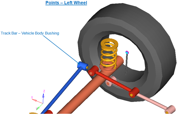
Left Side Principal Points – Rear Linked Solid Axle Suspension
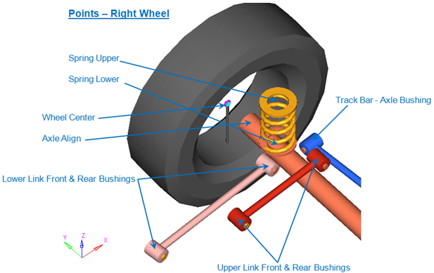
Right Side Principal Points – Rear Linked Solid Axle Suspension
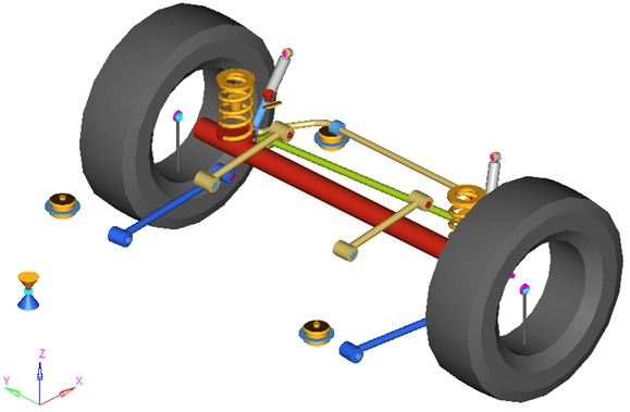
The Rear Linked Solid Axle suspension is comprised of the bodies shown in the image below:
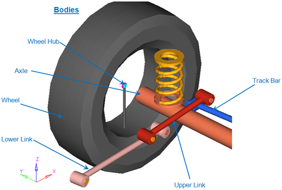
Bodies in Rear Linked Solid Axle Suspension
The figures below show the location of the joints and bushings in the suspension:
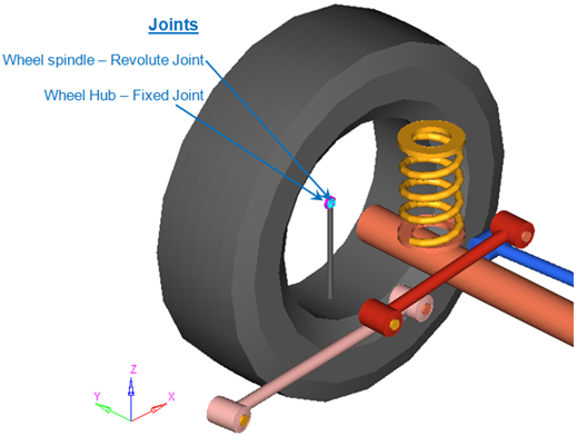
Joints in Rear Linked Solid Axle Suspension

Left Side Bushings – Rear Linked Solid Axle Suspension
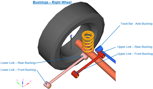
Right Side Bushings – Rear Linked Solid Axle Suspension
The linked solid axle suspension system can be used in either a half car or a full vehicle analysis. The default geometry and mass is that of a passenger car or light truck, but the model and data can be revised to reflect any size vehicle, from a large truck to a scale model car.
| • | The wheel is used to represent the mass of the tire and the rim. |
| • | The wheel hub is used to represent the mass of the wheel hub and any other components that rotate with the hub, such as a brake rotor. There are no graphic entities for the wheel hub. |
| • | The front and rear bushings for the respective links are defined such that they aligned parallel to each other. |
| • | The Center of Gravity (CG) of the parts is estimated from the geometry. The formulas are coded into the Point panel and can be seen via the graphical user interface. If exact CG locations are available, they should be entered as X, Y, Z coordinates instead of the estimated number. |
| • | Both the Wheel and Wheel hub parts use the Wheel CG location as the center of gravity. |
| • | When the suspension is built as a kinematic suspension, the track bar is removed since it would over constrain the axle. The bushings on the links are replaced with joints. |
| • | A wide variety of combinations of suspensions and subsystems can be built using the Assembly Wizard. You are encouraged to build systems and understand the resulting model using the graphical user Interface. |
| • | When building a new suspension model, build the model with all of the optional systems (stabilizer bar, etc) included in the model. Immediately turn off the systems using the Project Browser and run an analysis on the base suspension to ensure it solves properly. As data becomes available for the optional systems; activate those systems on and populate them with data. |
Fully populated Rear Linked Solid Axle Suspension model
The image below shows the MotionView Project Browser view of the systems in a fully populated rear suspension model. The Rear linked solidaxle susp system has five “child” systems.
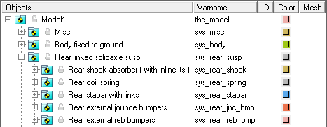
Browser view of the fully populated Rear Linked Solid Axle Suspension model
The jounce bumper curve data and the rebound bumper curve data files are stored in the Vehicle Library and are referred to by this model. A new file should be created and substituted for these files when actual data is available.
| • | Rear Twist Beam |
| • | Rear Solid Axle w/Leafspring |