Introduction
A Steer release in a turn event simulates a vehicle cornering at a constant radius and the dynamics of the steering wheel being released while in the corner. A Steer controller is used to drive the constant radius curve, a Drive torque controller is used to maintain a constant speed, and standard outputs for the vehicle and tires are included in the Tire system and the Output Requests system. A plot template is available to plot the results.
Steer Release in a Turn Event
Top View of a Steer Release in a Turn
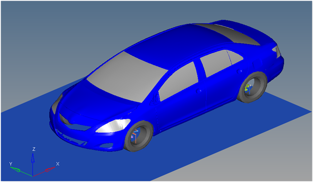
Vehicle Model with Body Graphics
Detailed Description
The Steer release in a turn event is designed to work with a full vehicle model that has been built through the MotionView Assembly Wizard. The event should attach to the model automatically when added through the Task Wizard. The event can be used with models built manually, as long as the attachment scheme in the event is strictly followed.
This event is used to determine vehicle response to releasing the steering wheel while cornering. The event setup and sequence is as follows:
Input
|
Units
|
Description
|
Lateral Acceleration
|
“G”s
|
Lateral Acceleration of the vehicle during the constant radius portion of the event. The Lateral Acceleration and the Circle Radius are used to calculate the vehicle speed.
|
Circle Radius
|
Meters
|
Radius of the constant radius circle. The Steer controller attempts to follow this radius using the CG of the vehicle body location.
|
Turn Direction
|
Left or Right
|
The radius is either a left or a right turn.
|
Steer Release Time
|
Seconds
|
The time in the event that the steering wheel is released. The event ends five seconds after the release of the steering wheel.
|
Vehicle Velocity
|
Miles per Hour
|
The velocity of the vehicle. The velocity is calculated using the desired lateral acceleration and the radius of the corner.
|
Ground Z Coordinate
|
Z Height of Ground
|
The height of the ground. Calculated using the left front wheel center of gravity and the tire Static loaded radius as entered in the tire data Form.
|
The event sequence is as follows:
Time
|
Event
|
Description
|
0
|
Static
|
Vehicle solves static analysis.
|
0+
|
Joint Release
|
Joints holding the vehicle to ground and holding the wheels fixed to the spindle are released so the vehicle can run dynamically. Commands that perform this are in the vehicle event template.
|
0++
|
Dynamics
|
Vehicle begins driving dynamically along the entry length section of a straight road.
|
Varies
|
Enter Constant Radius
|
Vehicle enters the constant radius corner and should settle into steady state cornering prior to the steering wheel being released.
|
Steer Release Time
|
Steering Wheel is Released
|
The Steer controller no longer steers the vehicle. Steering wheel is free to rotate on its own.
|
Steer Release time +5 sec
|
Event End
|
The event ends. You can modify the end time by editing the event template.
|
The event sequence is described in the chart below:
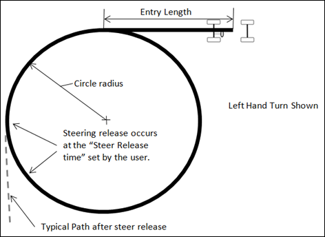
Figure - Event Diagram - Steering Release in a Turn
The Steer controller drives the vehicle on the straight and the constant radius path by applying motion to a joint at either the steering wheel or the steering rack input shaft (if no steering column is included). The controller is disabled at the Steer Release time.
The Drive torque controller is included to maintain constant speed during the entire event. The Drive torque controller applies a torque to the drivetrain and uses a P-D controller (with user-defined parameters) to control the speed of the vehicle.
The entry length straight road section is included to allow the vehicle model to settle into steady-state, straight line driving. The vehicle turns into the constant radius corner and should be allowed to reach steady-state cornering before releasing the steering wheel.
The steering controller is turned off at the Steer release time and the vehicle responds to the release using the physics in the vehicle model. The event is defined to end five seconds after the steer release. The end time can be changed by editing the event template.
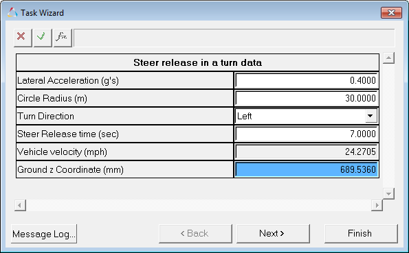
Steer Release in a Turn Data Dialog
Miscellaneous Notes
| • | Steering returnability, which is what this test measures, is affected by the internal friction in the rack and pinion steering system. The vehicle library models do not contain friction as a standard element. |
| • | The Steer Release time should be set so the vehicle is in steady state cornering and most transient responses have settled out. To set it properly, run the event once with a high value of the steer release time. |
| • | The default settings of the event result in a vehicle that drives approximately ¼ of the constant radius circle when the steering wheel is released. |
| • | Yaw velocity of the vehicle is a good measure of how straight the vehicle is driving after the release of the steering wheel. |
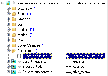
The entities in the event are displayed in the MotionView Project Browser as shown in the image below:
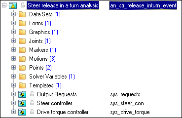
Project Browser View - Forms - Steer Release in a Turn Analysis
Nine types of modeling element containers (Datasets->templates) are used to define the event (see below). Three sub-systems (Output Requests, a Steer controller, and a Drive torque controller) are also included in the event.
The event uses the standard event attachment. The attachments resolve automatically if the model is built through the Model Wizard. The attachments contain the minimum data the event needs to run the analysis. The attachments are standard for most events.
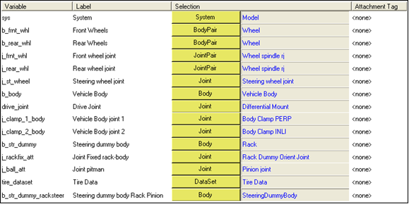
Steer Release in a Turn Event - Attachments
|
One dataset is used in the system and it contains the data used to describe the Steer release in a turn event. The event allows you to set the Lateral Acceleration, Circle Radius, Steer release time and the Turn Direction (left or right). The initial vehicle velocity, wheel rotational velocities, and ground height are calculated values and should not be changed.
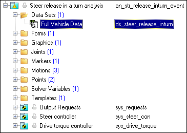
Project Browser View - Datasets - Steer Release in a Turn Analysis
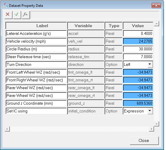
Dataset Property Data Dialog - Steer Release in a Turn Analysis
|
The Form is the only place that you should change the data of the event. Lateral Acceleration, Circle Radius, Turn Direction and Steer release time are the parameters that can be changed. The Ground z Coordinate is a calculated value and is calculated using the wheel CG Z location and the tire rolling radius from the Tire Data Form.
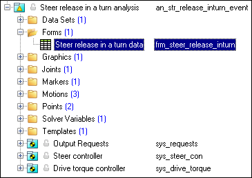
Project Browser View - Forms - Steer Release in a Turn Analysis
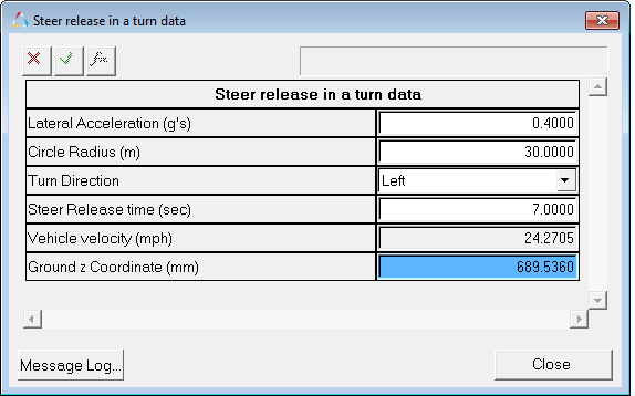
Steer Release in a Turn Data Analysis - Form Dialog
|
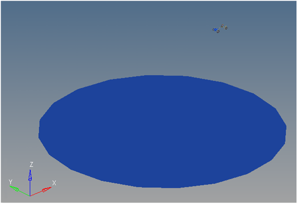
One graphic is defined in the event. The graphics define the road surface graphics and should not require any user input. A full description of the graphics can be found here.
Skidpad graphics are included to illustrate the path being driven and are defined parametrically using the data in the event data Form. Skidpad graphics should never require editing unless the event is being fundamentally changed.
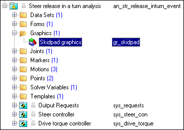
Project Browser View - Graphics - Steer Release in a Turn Analysis
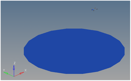
Skidpad Graphics
|
A ball joint is included in the Steer release in a turn event. The joint attaches a dummy body to the steering rack. The joint is included to make certain events work in ADAMS. Attach the dummy body to the steering rack if building a model manually.
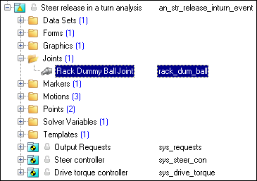
Project Browser View - Joints - Steer Release in a Turn Analysis
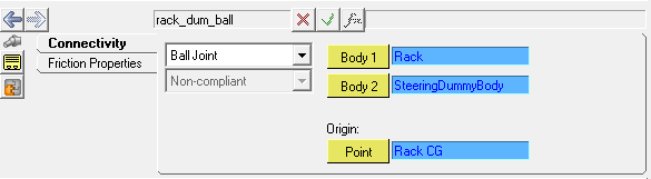
Joints Panel - Steer Release in a Turn Analysis
|
One marker is included in the event. The path origin is the origin of skidpad graphics and is parametrically defined to be the CG of the vehicle body. The markers refer to points and the points contain the parametric logic.
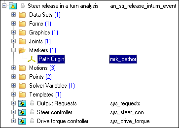
Project Browser View - Markers - Steer Release in a Turn Analysis
|
Three motions are included in the event. The steering motion to the vehicle is provided by the steering controller and acts on a revolute joint that connects the steering column to the vehicle body. If a steering column is not included in the model, the joint acts between the steering rack input shaft and the vehicle body.
The Front and Rear Wheel Motions act on the wheel spindle revolute joints that connect the wheel hub to the knuckle. The motion is initially zero (fixing the wheels to the knuckle) so the model converges statically. The motions are deactivated after the initial static analysis to allow the tires to rotate during the dynamic analysis.
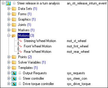
Project Browser View - Motions - Steer Release in a Turn Analysis
|
Two points are defined in the event. All points are used to create the skidpad graphics. The points contain parametric logic to define their X, Y, and Z locations. You should not need to modify any points.
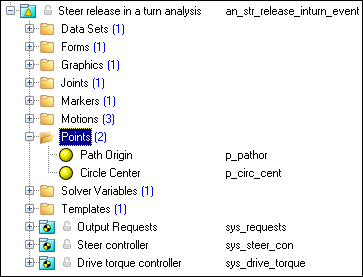
Project Browser View - Points - Steer Release in a Turn Analysis
|
The Steer release in a turn event consists of only one solver variable, the Steer Path Variable, which calls a user subroutine to apply an input at the steering wheel in order to follow a desired path.
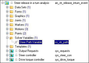
Project Browser View - Solver Variables - Steer Release in a Turn Analysis
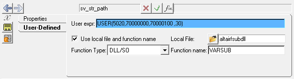
Solver Variable Panel - Steer Path Variable
The numbers in the solver variable USER subroutine call are as follows:
Number
|
Description
|
5020
|
The Branching ID. 5020 is a Steer release in a turn event.
|
70000000
|
The ID of a solver array containing Driver Model Controller data. The array is in the Steer Controller System.
|
70000100
|
The ID of a Vehicle Data Array containing vehicle information. The array is in the Steer Controller system.
|
30
|
The value of the Circle Radius.
|
|
The template is solver specific and only the MotionSolve template is documented. The template is inserted in the solver deck after the </Model> command and controls the execution of the event.
Project Browser View - Templates - Steer Release in a Turn Analysis
The template for this event is shown below:
<ResOutput
angle_type = "YPR"
/>
<ResOutput
mrf_file = "TRUE"
/>
<ResOutput
plt_file = "TRUE"
/>
<H3DOutput
switch_on = "TRUE"
increment = "1"
/>
{if (tire_dataset.opt_omega.ival ==1)}
<!--Initial static analysis -->
<Simulate
analysis_type = "Static"
end_time = "0.0"
/>
{endif}
<Deactivate
element_type = "MOTION"
element_id = "{mot_frnt_wheel.l.idstring}"
/>
<Deactivate
element_type = "MOTION"
element_id = "{mot_frnt_wheel.r.idstring}"
/>
<Deactivate
element_type = "MOTION"
element_id = "{mot_rear_wheel.l.idstring}"
/>
<Deactivate
element_type = "MOTION"
element_id = "{mot_rear_wheel.r.idstring}"
/>
{if (tire_dataset.opt_omega.ival ==2)}
<!--Initial static analysis -->
<Simulate
analysis_type = "Static"
end_time = "0.0"
/>
{endif}
<Deactivate
element_type = "JPRIM"
element_id = "{j_clamp_1_body.idstring}"
/>
<Deactivate
element_type = "JPRIM"
element_id = "{j_clamp_2_body.idstring}"
/>
<Motion_Joint
id = "{wh_motion.idstring}"
expr = "VARVAL({sv_path.idstring})"
/>
<Simulate
analysis_type = "Transient"
end_time = "{ds.release_tim.value}"
print_interval = "0.02"
/>
<Deactivate
element_type = "MOTION"
element_id = "{wh_motion.idstring}"
/>
<Reference_Variable
id = "{sv_path.idstring}"
type = "EXPRESSION"
expr = "0.0"
/>
<Simulate
analysis_type = "Transient"
end_time = "{{ds.release_tim.value}+5}"
print_interval = "0.02"
/>
<Stop/>
|
|
References:
ISO +17288-1-2011 - Passenger cars - Free-steer behaviour - Part 1: Steering-release open-loop test method.


