Engineering Solutions

Assembly Browser Context Menu

Assembly Browser Context Menu

Previous topic Next topic Expand/collapse all hidden text  

Assembly Browser Context Menu

Previous topic Next topic JavaScript is required for expanding text JavaScript is required for the print function  

You can access advanced Assembly browser options from the context menu, when you right-click on a module in the browser. Use the options in the context menu to:

hmtoggle_plus1greyLoad BOM

PLMXML is the exchange format that transports the assembly information between Teamcenter and HyperMesh.

To load a PLMXML (.xml) file:

1.Right-click in the Assembly browser and select Load BOM from the context menu. The XML Import dialog appears.

assembly_browser_4

2.In the File Name field, navigate to your working directory and open the .xml file.
3.Click OK. HyperMesh imports the .xml file into the Assembly browser.
Note:In the Assembly browser, many operations are recursive, meaning that when you select a module and perform an operation on it, the same applies to all the children modules.

Representations are various versions associated with any module. You can use any of these at a given time. Basically, each representation has a file associated with it, and that file for the current representation will be imported into HyperMesh when you import a module.

A representation cannot have more than one file attached to it.

When you select a representation, it is set as the current representation for that particular module. When that module is imported into HyperMesh, the file associated with that particular representation is imported into HyperMesh. If you want to import a different file, change the representation to the one that contains the desired file and then import that particular module.


hmtoggle_plus1greySave WIP

To save your work-in-progress data, select Save WIP from the right-click context menu. Once you select Save WIP, HyperMesh saves a UDMXML file in the assembly working directory. This file captures the assembly structure state, including the current representations and all metadata values. After you have saved your work-in-progress to the UDMXML file, you can safely close the Assembly browser or HyperMesh.

Note:Saving the HyperMesh file by clicking File > Save from the menu bar, will not save the assembly structure or state.

To continue working with a saved UDMXML assembly BOM, load the WIP BOM using the Load BOM process. Select the saved WIP UDMXML BOM instead of the original PLMXML BOM.


hmtoggle_plus1greySave PLMXML

In order to import the meshed parts into Teamcenter, an updated PLMXML .xml file is needed. This file captures any changes that were made to the assembly after it was imported into HyperMesh. If the original .xml file contained only CAD parts with thickness and material attributes, and if you meshed these parts in HyperMesh and made changes to the thickness for certain parts, then the delta PLMXML file will capture the changes made.

To create a delta PLMXML file and a monolithic HyperMesh or solver file, select the Module Model module and then select Save PLMXML from the right-click context menu. The type of monolithic file HyperMesh creates is determined by the settings you selected within Teamcenter prior to exporting the original PLMXML file.

Teamcenter uses the delta PLMXML file to update metadata and files when you upload the updated assembly file. You cannot use the delta PLMXML file to save work-in-progress information, or load it into the Assembly browser.

You cannot save the HyperMesh file by clicking File > Save from the menu bar, because it will not save the assembly structure or state. To save your work-in-progress data, select Save WIP from the right-click context menu.


hmtoggle_plus1greySet Rep

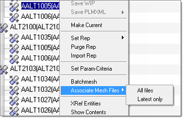
To change the representation of a module, right-click on the representation and then select Set Rep from the context menu.

assembly_browser_5

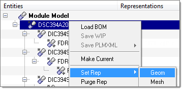
When you select Set Rep, two types of representations categories appear: Geom and Mesh.

Geom

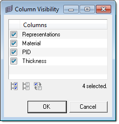
Sets the geometry as the current representation. The type of CAD that is set as the current representation is based on the order of preference as set in the config file, which is provided by Teamcenter.

Mesh

Sets the mesh file as the current representation. The last representation in the list of mesh representations is set to current.

A module can have multiple representations associated with it. The representations are basically categorized into two types, Geom and Mesh. The Geom representations have CAD files associated with them and Mesh representations have mesh files associated with them.

Generally, CAD representations are provided along with the BOM file and the representations are added based on a failing order. The format that is on top of failing order is associated first and so on.

Most of the time, the mesh representations are created after operations likes Batchmeshing, mesh editing, penetration checks, and so on. The last representation of Mesh type is generally the latest representation and is of primary concern.

When you select Set Rep > Geom, HyperMesh searches for a list of Geom representations and sets the first one in the list as the current representation. This is in alignment with the failing order as the representation on top of the failing order is set as current.

When you select Set Rep > Mesh, HyperMesh searches for a list of Mesh representations and sets the last one in the list as the current representation. This way, you set the last created representation as current.

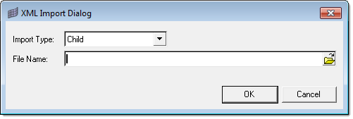
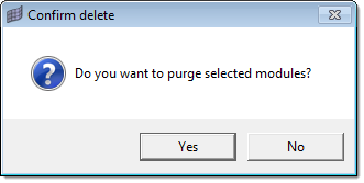
There might be representations that do not have any files associated with them, which may come with a .xml file. HyperMesh ignores these representations when searching for the appropriate Geom/Mesh representations. In a case where a representation of a selected type is not present, HyperMesh does not change the current representation. For example, if the current representation is of type Mesh and there is no Geom representation associated with the module, when you select Set Rep > Geom , the current representation does not change and HyperMesh leaves it as type Mesh. If the current representation does change, HyperMesh purges the module as well.


hmtoggle_plus1greyPurge Rep

To remove all of the contents under the modules from the current HyperMesh session, select Purge Rep from the right-click context menu.

Before you are able to remove all of the contents under a module, the Confirm delete dialog appears asking if you want to purge the selected modules.

assembly_browser_6

HyperMesh will still maintain the representation in the hierarchy, and you can import when desired. When you purge a module, all of the changes you have made to the contents of the module will be lost permanently. HyperMesh will not automatically update the files in the current representation with the updated content. To retain the changes, you must save the modules as a HM file (or Solver file) before purging.


hmtoggle_plus1greyImport Rep

To import the associated representation into HyperMesh, right-click on a representation and then select Import Rep from the context menu. If there are children modules in the module you select, then all of the children will be imported.

In general the operations in the right-click context menu work on everything under the selected module.


hmtoggle_plus1greySet Param-Criteria

To set individual mesh parameter and criteria for selected module(s), select Set Param-Criteria from the right-click context menu.

After you select Set param-Criteria, the Select Mesh Parameters & Criteria dialog appears.

assembly_browser_7

From the Select Parameter list, select a parameter to assign to the selected module.


hmtoggle_plus1greyBatchmeshing

To batchmesh a module or modules, right-click on a module or modules and then select Batchmesh from the context menu. After you select batchmesh, the Batchmesh Representation dialog appears.

assembly_browser_8

In the Batchmesh Representation dialog, you can:

Select one of the following:

Generate, if not present – Create a new mesh for the given module using the selected parameter and criteria files, as long as a mesh for the given module and selected parameter and criteria files does not already exist.
Force Generate – Create a new mesh for the given module using the selected parameter and criteria files, even if a mesh for the given module and selected parameter and criteria files already exists.


Select one of the following:

Use Current – Uses the current representation as input to the batch mesher for creating the new mesh.
Geom – Uses the geometry representation as input to the batch mesher for creating the new mesh.
Mesh – Uses the existing mesh representation as input to the batch mesher for creating the new mesh.


Click Advanced Options to edit the following:

Respect module attributes if exist (discipline and mesh quality)

If module attributes exist and you would like to leave them as is during batchmeshing, select this check box.

CPUs to use

In order to run the BatchMesher faster on a system with multiple processors, enter the number of CPU values. This will run that many instances of batchmesher.

Show Batchmesher

To show the BatchMesher GUI instead of running the batchmesh in the background, select this check box.

Keep BatchMesher open after completion

To keep the BatchMesher open after the batch meshing process is finished, select this check box.

To start the BatchMesher, click Run. The following messages appear during the batch meshing process:

assembly_browser_9

Message displayed when BatchMesher is running in GUI mode

assembly_browser_10

Message shown when BatchMesher is running in background


hmtoggle_plus1greyAssociate Mesh Files

To associate mesh files for modules shown in the Assembly browser, right-click on a module and then select Associate Mesh Files > All files or Latest only from the context menu.

assembly_browser_11

When you select Associate Mesh Files, two additional options appear: All Files and Mesh.

All files

Assigns all files to the module, if several representations exist for a particular module.

Latest only

Sets the latest file (based on time stamp) as the only representation associated with the module.

Associate mesh files search the mesh files based on their CAD file name. If the module does not have any CAD files associated with it, then no file will be associated. When HyperMesh is associating mesh files, a CAD representation is necessary. For example, when the initial PLMXML file contains only solver/hm files, nothing can be associated.

The associate mesh file also searches the mesh files based on their extension and CAD file name. If HyperMesh associates the wrong mesh file, select Associate Mesh Files > All files and then locate the appropriate file.


hmtoggle_plus1greyShow Contents in a Module

To display all of the contents in a selected module, select Show Contents from the right-click context menu.

After you select Show Contents, HyperMesh opens a new Contents browser, which displays all the contents in the selected module.

hmtoggle_plus1greyExport a Model

To export a model for a given module, select Export Model > HM File or Solver File from the right-click context menu.

You are able to save module information in the following files types:

HM File: Saves all of the information about a particular module into a HyperMesh file and associates that file as a representation for the selected module.
Solver File: Saves all of the information about a particular module into a Solver file and associates that file as a representation for the selected module. The file format is determined by the current user profile.

You are only able to save a file when entities are organized under the module and the current representation of the module is not empty. After HyperMesh creates the new file, it is set as the current representation to the module.


hmtoggle_plus1greyShow, Hide, or Isolate Modules

To show, hide, or isolate a module in the graphics area, right-click on the module and then select Show, Hide or Isolate from the context menu. Show will bring the module to the display; Hide will hide the module; Isolate will turn off all other modules and display the selected one.

Note:This operation is recursive, meaning that when you select a module and perform an operation on it, the same applies to all the children modules.


hmtoggle_plus1greyRealize Connectors

To import and realize the connectors from a .mcf file, click assembly_browser_12 in the Assembly browser. The Mcf Import dialog appears:

assembly_browser_13

In the MCF File field, navigate to your working directory and open the connector file. To automatically realize the connectors when you import the connector file, select the Realize on import check box.

To view the connectors that you have imported, click View > Connector Browser from the menu bar.


hmtoggle_plus1greyShow All Attributes in a Module

To display all of the attributes in a selected module, select Show All Attributes from the right-click context menu. After you click Show All Attributes, HyperMesh opens a dialog that displays all the attributes in the selected module.


hmtoggle_plus1greyCollapse and Expand All Modules in the Assembly Browser

To collapse or expand all of the modules models in the Assembly browser, select Collapse All or Expand All from the right-click context menu. To close all of the modules models in the tree structure and only display the top-most module, select Collapse All. To open all of the modules models in the entire tree structure and expose every item nested at every level, select Expand All.


hmtoggle_plus1greyConfigure the Assembly Browser

To change what columns display in the Assembly browser, select Configure Browser in the right-click context menu.

After you select Configure Browser, HyperMesh opens the Column Visibility dialog. From this dialog, select the check boxes of the columns you wish to display.

assembly_browser_14