|
»Click here to display Table of Contents«
|

Auto Contact |

|

|

|

|
|
Auto Contact |
|
|
|

|
|
»Click here to display Table of Contents«
|
Auto Contact |
|
|
|
|
|
Auto Contact |
|
|
|
|
Location: Utility menu, Tools > Auto Contact. To access this tool, you must first load the Nastran user profile.
The Auto Contact tool lets you create one or more contact interfaces between parts of your model. Based on a proximity distance, the Auto Contact tool searches through the parts that you select and automatically creates new contact surfaces and contact interfaces between them. The Auto Contact tool displays and organizes the contact entities inside of a temporary Auto Contact browser where you can review and adjust the contacts as needed before accepting any changes.
Auto Contact creates Nastran BCBODY-BSURF pairs and puts them into a Nastran BCTABLE card. You can select a variety of contact types from the drop-down list in the Auto Contact dialog. The interface type you select is used as the initial configuration for all found interfaces. You can edit the interfaces in the Auto Contact browser.
The BCBODY-BSURF surface group pairs are created as master and slave entities per each contact interface, with the following characteristics:
| • | Master and slave surfaces are automatically assigned based on the average element size of each surface: |
| - | The surface with the smallest, average element size is assigned as a slave, and the other as a master. |
| - | You can review and swap the master and slave assignments for each contact in the Auto Contact browser. |
| • | For 3D element faces, the surface normal direction points outward from the solid body. |
| • | For 2D elements, the surface normal direction is assigned according to element normals. You can review and reverse this information in the Auto Contact browser. |
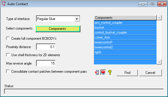
The Auto Contact dialog contains the following options:
Option |
Description |
||||||||||||||||
Type of interface |
This controls the contact type as defined by the IGLUE option inside of the BCTABLE card. The IGLUE options include:
Please refer to the MSC Nastran documentation for a detailed explanation. |
||||||||||||||||
Select components |
This directs you to the Component Selection panel, where you can select the components you want the Auto Contact tool to search through. |
||||||||||||||||
Create full component BCBODY's |
When activated, the Auto Contact tool creates BCBODY-BSURF pairs of the entire outer surface of the given components, instead of just the elements inside the contact area. When turned off (default), the BCBODY-BSURF pairs contain only the elements inside the contact area, as controlled by the Proximity Distance parameter. |
||||||||||||||||
Proximity distance |
This value specifies that the contact pairs generated between components are closer to each other by less than the specified proximity distance. |
||||||||||||||||
Use shell thickness for 2D elements |
If activated, the shell thickness values are used for 2D elements instead of the specified Proximity distance. 3D elements keep the specified Proximity distance. |
||||||||||||||||
Max reverse angle |
This is a maximum value that you specify. If the angle between the normals of two elements, or element faces within the proximity distance, exceeds the specified value, the elements are excluded from the contact. The default value is 15 deg. |
||||||||||||||||
Consolidate contact patches between component pairs |
When activated, the Auto Contact tool consolidates any separate contact patch areas that participate in contacts between the same two components, so that the final number of BCBODY-BSURF pairs in the model can be reduced. When turned off (default), each contact patch area is treated as a separate BCBODY-BSURF pair. |
||||||||||||||||
Find |
Executes the Auto Contact search between all of the components in the list. |
||||||||||||||||
Remove Selection Icon |
Removes the highlighted items from the selected components list. You can use the Ctrl and Shift keys to select multiple items in the list. |
||||||||||||||||
Review Selection Icon |
Highlights the selected items from the component table in the HyperMesh graphics area, while graying out other components. You can use the Ctrl and Shift key to select multiple items in the list. Right-click to return the model to normal display. |
||||||||||||||||
Help Icon |
Opens the Auto Contact online help. |
During the Auto Contact process, temporary components may be created for parts containing 3D elements. These temporary components are named using a preceding ^ symbol, and automatically contain extracted element faces needed for the contact creation process. Auto Contact cleans up and removes these temporary components when you finish or cancel the process. If you decide to export the model before accepting or canceling the process, HyperMesh excludes these temporary components from export.