Engineering Solutions

Contour Loads

Contour Loads

Previous topic Next topic Expand/collapse all hidden text  

Contour Loads

Previous topic Next topic JavaScript is required for expanding text JavaScript is required for the print function  

Use the Contour Loads utility to create contour plots of applied loads and boundary conditions contained within load collectors.

The Contour Loads utility consists of three sections: load collectors, contour options, and command buttons.

hmtoggle_arrow1Load Collectors Section

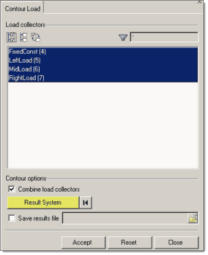
The Load collectors section lets you select load collectors to contour.  Every load collector in the current model’s database displays in the load collector list.  You can pick multiple load collectors by CTRL-clicking or SHIFT-clicking.

Filter buttons allow for additional selection control, including a name filter that uses standard filtering syntax.

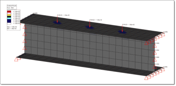
The Contour Loads utility generates a .res file that is automatically loaded into the Contour panel.  The .res file contains simulation results named after each load collector, unless you select the combine load collectors option in the contour options section.  If a load collector contains multiple load types, the simulation result will include multiple data types (that is load collector).  Different load types support different data types:

Load Types

Data Types

Acceleration, Force, Moment, Velocity

X, Y, Z, MAG (unsigned).

MAG is simply the magnitude of the X/Y/Z components

Pressures

X, Y, Z, MAG, Signed MAG.

MAG is simply the magnitude of the X/Y/Z components.  “Signed MAG” computes the dot product of the X/Y/Z components with the element normal to give a sign to the MAG value.  If the dot product is >=0, the sign is positive, otherwise the sign is negative.  MAG and “Signed MAG” always have the same absolute value.

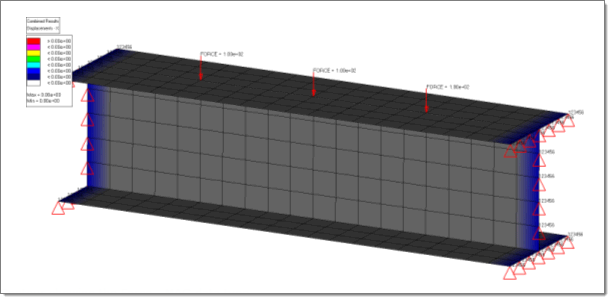
Displacements, Rotations

X, Y, Z.

Coming from constraints, rotations and displacements each have 3 degrees of freedom..

Temperatures, Fluxes

Temperature and Flux (single data types only).

Comments:        

In the Abaqus user profile, support is available for the *FILM, *RADIATE and *SFILM cards. *FILM and *RADIATE are supported for pressures assigned directly to elements only. *SFILM is supported for groups defined using elements, components or sets only, but only applies the contour to shell elements within the group, ignoring any non-shell elements within it. *SFILM has two possible data types: *SFILM - Film_Coeff and *SFILM - Sink_Temp.
The loadstep names in the results file are the selected load collector names.  If the Combine load collectors option is checked, only a single loadstep is generated in the results file named Combined Results.
In all cases, a data type is only created if there is an applicable result for that data type.  Some data types may not always be created.  For example a force in the X direction will not create the Y and Z data types, but will create X and MAG.
If a non-rectangular local coordinate system is selected, the X/Y/Z labels change to R/T/Z (cylindrical system) or R/T/P (spherical system).


hmtoggle_arrow1Contour Options Section

The Contour options section allows you to control options for generating contour data from the selected load collector(s).  Contour options include:

Combine load collectors: linearly superimposes all loads of the same load type from all selected load collectors into one simulation, named "Combined Results" within the .res file.  If two load collectors are selected, and both contain force data, Engineering Solutions linearly superimposes their forces and plots them in one contour, as opposed to a separate force contour for each load collector.  Loads are summed — or in the case of constraints, only the maximum constraint value is used.

Result System: defines the coordinate system in which the simulation data is transformed into and output to the contour.  If a system does not currently exist, one can be created by clicking the Proceed button without selection of a coordinate system.  If no results system is specified, Engineering Solutions uses the system that the loads were created in.  This option is not available for flux or temperature load types.
Save results: this option allows you to store the contour results in a HyperMesh results file (.res) using a specific file directory and filename.  These results can then be loaded into Engineering Solutions or HyperView for review.
Upon clicking Accept, the Contour panel opens so that you can select the appropriate simulation and data type.  The simulation corresponds to the load collector, and the data type is the list of load type(s) and components contained in the selected simulation.

Here is a sample GUI setup and contour for the model shown below:

bcscontourexample1

bcscontourexample2

The Contour Loads Utility

bcscontourexample3

Contour showing the Force - MAG data type.

bcscontourexample4

Contour showing the Displacement - X data type.


hmtoggle_arrow1Command Buttons

Three command buttons at the bottom of the tab perform the following actions:

Accept: Activates the Contour panel, where the selection of a simulation and a data type within that simulation are required to produce the desired contour.  The simulation corresponds to the load collector, and the data type is the list of load types contained within the selected load collector(s).

Each simulation corresponds to one load collector.  If multiple load types are contained inside a load collector, there will be multiple data types available.  When using the Combine load collectors option, only one simulation will exist with the name "Combined Results" as discussed above.

Reset: Clears all of the entry fields on the tab so that you can start over.
Close: Closes the tab without performing the contour plot.


See Also:

Contour panel

Alphabetical List of Panels