The BCs Manager tool can be used to create boundary conditions of any load collector type other than ACTIV. This tool combines required actions from several panels into one convenient tab interface, including the ability to create a boundary condition from both sets and individual nodes.
To display the tool, select BCs Manager from the Utility menu. The tool appears as a tab in the tab area.
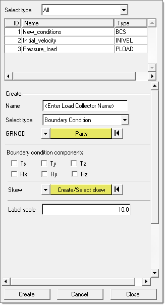
| 1. | To begin creating a new boundary condition, select the type of boundary condition you want to create in the Select type field. |
| 2. | In the Name field, type a name for the load collector. |
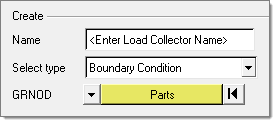
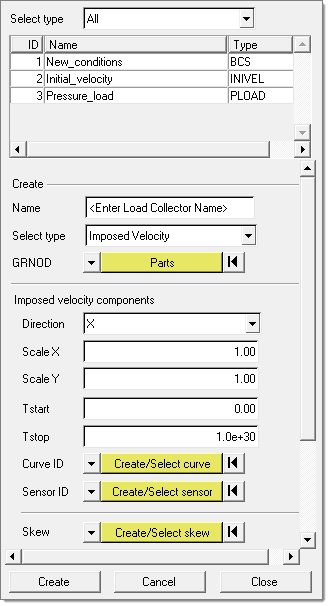
| 3. | Select the type from the drop down menu in the Select type field. Based on the type selected, the options that display may change. |
| 4. | Use the selectors to pick sets and/or individual nodes to define boundary conditions. The switch allows you change the selector to access parts, nodes, materials, properties, GRNOD (set), and GRNOD (box). Pick the type of entity to be selected from the pull down menu and click the yellow button to open the Selector panel. |
| 5. | Enter the loading conditions in the options. Empty fields require user input, and yellow buttons provide links to another entity that need to be linked; namely curve, system or sensor. Each yellow tab has two options: create /select and select. |
| • | Create/select allows you to directly create the entity from this GUI |
| • | Select allows you to select an entity already defined |
| 6. | Click Create to create the database with the boundary condition data entered. Click Cancel to cancel the creation and Close to close the dialog. |
|
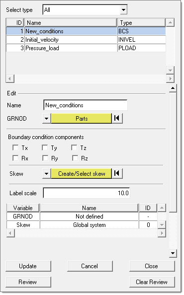
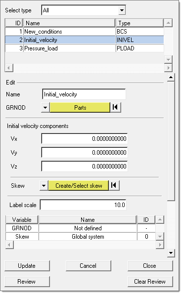
| 1. | Highlight a boundary condition in the list to display its properties. This opens the Review (editing) mode of the dialog, as shown below. |
| 2. | In Review mode every defined entity/entry in the field can replaced with new entity or modified. To replace the entity on which boundary condition is define, set the GRNOD tab to the desired entity to be selected and make the selection. The selection will replace the existing entity on which the BC is defined. Similarly the curve, system and sensor can be changed. |
| 3. | The table appears with list of entities that are referred in the selected boundary condition. To edit the existing entity, select the entity, right-click it and select edit. This opens a corresponding panel with editing features. |
| • | Update: update the changes made to the selected boundary condition. Click return to go back to Create mode. |
| • | Cancel: Nullify all updates made to the selected boundary condition. Click return to go back to Create mode. |
| • | Close: Nullify all updates to the selected boundary condition and close the dialog. |
| • | Review: Highlight the entities on which the selected boundary condition is defined. |
|
The table in the dialog lists the boundary conditions in the model by default. This can be limited to the desired boundary condition using the Select type option on the top of the table.
Right-clicking on each entity in the table provides the following functions:
| • | Refresh list: Refreshes the table based on the option in the Select type field. |
| • | Card edit: Opens the selected boundary conditions's card image panel. |
| • | Delete: Deletes the selected boundary condition. |
| • | Review: Highlights the entities on which the selected boundary condition is defined and grays out the others. |
| • | Clear review: Returns the graphics window to regular mode. |
| • | Show all: No pre-selection is needed. Displays the part on which the boundary conditions in the table are defined and shows the load with handles. |
| • | Show: Displays the part on which the selected boundary condition is defined (if hidden) and shows the load with handle. |
| • | Isolate: Isolates the part on which the selected boundary condition is defined in the graphics and shows the load with handle. |
|