The following flow chart outlines a four-stage process used to select the best routine for bolt realization.
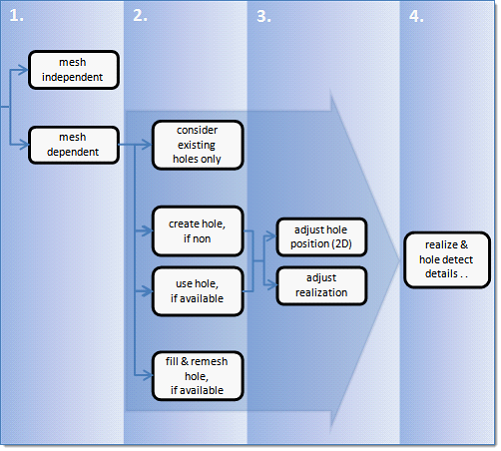
In stage 1, select the type of realization.
mesh independent
|
Use for realizations which do not need a node connection, and the connection is primarily defined via a solver-specific card or the nodes which need to be connected are defined by a cylinder, such as Bolt (cylinder spring) for RADIOSS.
For all mesh independent bolt realization types a cylinder is defined. Bolt hole detection is not performed because holes are not required. All of the nodes inside the cylinder are considered part of the bolt realization unless they also belong to a link defined on the connector.
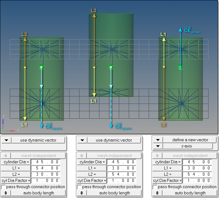
The cylinder dimension is primarily defined by its diameter, length L1 and L2.
| • | L1 points in the same direction as the connector vector and describes the distance from the connector position to the first end of the cylinder. |
| • | L2 points in the opposite direction and measures the distance between the connector position and the second end of the cylinder. |
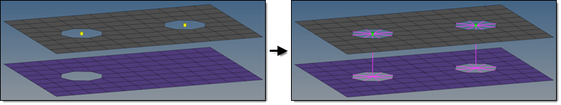
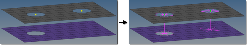
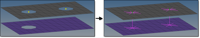
Therefore, the connector vector is essential for these types of realizations. See the image below for further explanation.
If a vector is not predefined and is determined dynamically, the vector will always point from the connector position to the projection point on the farthest link. In the image below, dynamic vectors have been used in the left and the middle examples. Interchanging the values for L1 and L2 leads to very different realizations. By comparison, the rightmost example uses the same values for L1 and L2 as in the middle example, but the result looks better because of the predefined connector vector in the global z-direction.
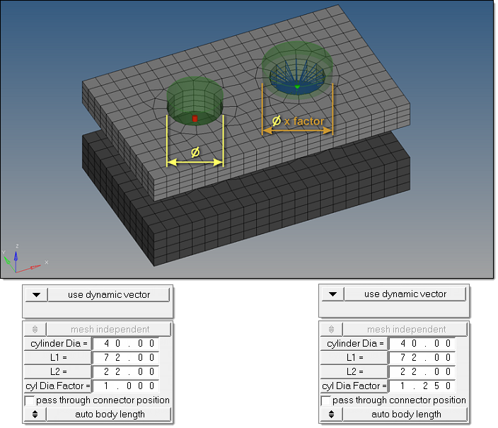
In some automated processes the cylinder diameter is automatically set to the bolt shaft diameter. This leads to failed cylinder bolts when the holes are properly modeled because the defined cylinder does not contain nodes. In such cases the cylinder diameter factor has been introduced; this factor is set to 1.0 by default and is a multiplier for the cylinder diameter to increase the final cylinder diameter when necessary.
| Note: | The cylinder diameter as well as the cylinder diameter factor can be reviewed and modified in the Connector browser. Connectors can also be rerealized with modified cylinder diameters and cylinder diameter factors without updating L1 or L2 in the browser. This is not possible from the panel. |
|
|
|
mesh dependent
|
Use for all other cases.
|
In stage 2, if you selected mesh dependent, you must determine:
| • | Is the existence of holes in each layer requested upfront? |
| • | How should the 2D mesh be prepared before the final realization is performed? |
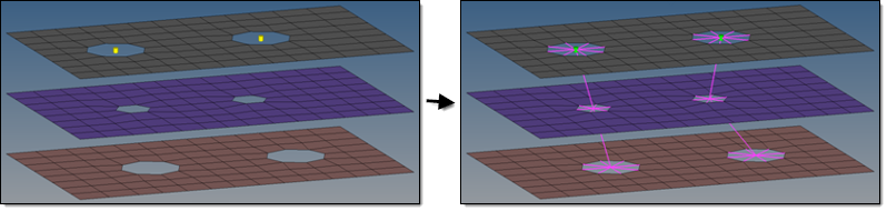
In the past a bolt realization always required a hole for each layer in the initial mesh. This is no longer necessary for 2D meshes because the imprint capability punches the needed holes into the mesh before the final realization is performed, enabling the mesh to be manipulated in a pre-step. This makes it possible to punch holes, move holes, close holes, create washers, and so on.
Select one of the following:
Consider existing holes only
|
A minimum of one hole per layer must be available in the origin mesh. If holes do not exist the realization will fail. This is the default method and must be used for any type of solid meshes.
|
Create hole, if none
|
This hole detection algorithm does not need to find a hole in each layer. If there are not any holes on a certain layer, they will be punched into that layer at the position of the projection point. The diameter of the new hole is defined on the Realization Details subpanel. This method is used if the model does not contain the appropriate amount of holes per bolt, but holes are required for specific realization types.
|
Use hole, if available
|
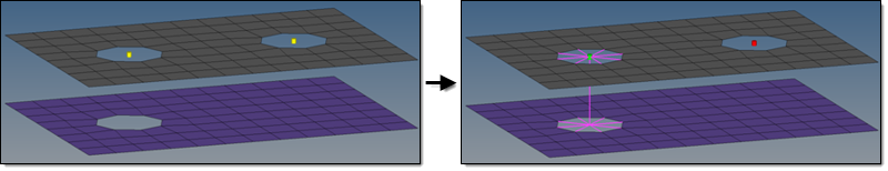
Creates hybrids (hole on one side only), but other combinations are allowed. On the mesh side (no hole), the connection is realized via the head elements defined in the chosen realization type. The head element(s) is/are created between the appropriate body element node and the nodes inside the diameter (no hole connection dia) defined on the Realization Details subpanel. This option is used for realization types which are not eager for holes.
|
Fill & remesh hole, if available
|
Use this option when you do not want the shape of holes to interfere with the mesh flow in the bolt region. The detected holes are closed and a remesh of the new elements and a few additional rows of adjacent elements is performed. The connection is realized via the head elements defined in the chosen realization type. The head elements are created between the appropriate body element nodes and the nodes inside the diameter (no hole connection dia) defined on the Realization Details subpanel.
|
| Note: | The hole detection mechanism for the last three options has been enhanced and takes into account a cylinder which is defined in the Hole Detection Details subpanel. The hole consideration cylinder option can be defined as a factor of the no hole connection dia option or as an exact diameter. Principally holes which are inside or touching the cylinder can be detected, but the hole consideration is reduced to one hole per link per connector. Additionally holes need to fit to the requested dimensions, which are also defined in the Hole Detection Details subpanel. |
|
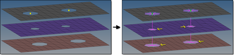
In stage 3, for the create hole, if none and use hole, if available options, in principal, a mesh modification including a hole movement is allowed. Therefore, you can determine whether to adjust the hole(s) or to adjust the realization.
| • | Adjust hole position (2D) |
|
Moves the center of a hole into the position of the projection point.
|
|
Hole positions are not modified, enabling the realized elements to compensate the nonaligned centers of holes.
|
Stage 4 cannot be skipped as it has great influence on stages 2 and 3, which is expressed by the large arrow underlying those stages in the flow chart.
This stage contains all realize and hole detection details which need to be known before the final realization is done. The realize and hole detection subpanel can be accessed by clicking realize & hole detect details in the bolt and realize subpanels. This subpanel is organized into two additional subpanels: hole detection details and realization details.
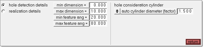
Dimension and Feature Angle
The minimum and maximum dimensions define which holes should be considered during bolt realization. The minimum and maximum feature angle define the features to be considered as hole edges for solid elements.
Hole Consideration Cylinder
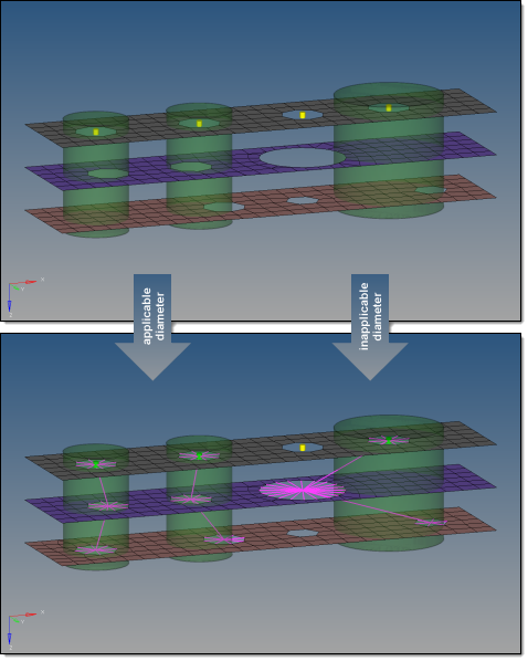
Not all of the holes found in the given connector tolerance can necessarily be considered for the various bolt realizations.
| • | The connector tolerance, especially when set to a large value, detects many holes. To prevent detecting holes which are far away from the connector position and are not aligned with the other hole(s), the consideration cylinder excludes outer holes from the detection. |
| • | Since the existence of a hole is not necessarily requested anymore, a space has to be defined where the holes are expected to be. It is no longer sufficient to use just the connector tolerance, therefore the hole consideration cylinder performed along the projection path becomes necessary. All of the holes the cylinder touches or contains can be considered for the various bolt realizations. |
Define cylinder diameters in the following ways:
| • | auto cylinder diameter (factor) |
|
Factors given diameters, which include: create hole diameter (2D), create/adjust hole diameter (2D), adjust hole diameter (2D), and no hole connection diameter. The first available diameter is used. The default factor is 1.5.
|
|
Specify an exact diameter. The default diameter is 15.0
Note: The hole consideration cylinder parameter is not offered when using the option to consider existing holes only.
|
|
Contains additional information about the exact treatment of holes and no holes, if the bolt realization is performed. Dependent on the options selected in stage 2, varying subsets of the options in the Realization Details subpanel are offered.
Diameter and Adjustments:
| • | create hole diameter (2D) |
|
Creates new holes with the diameter specified. Used if holes are required by the option create hole, if none.
|
| • | create and adjust hole diameter (2D) |
|
Creates new holes with the specified diameter and adjusts existing holes with the specified diameter, which leads to bolt realizations with the exact same diameter on all links. Used if holes are required by the option create hole, if none.
|
| • | adjust hole diameter (2D) |
|
Adjusts existing holes to the specified diameter. The do not adjust hole diameter option switches off the adjustment and uses the holes with their origin size. Used if holes are not necessarily required when using the use hole, if available option, but the existing holes need to have a specific diameter.
|
| • | no hole connection diameter |
|
Connects a link without an available hole by joining the nodes found inside the circle with the specified diameter around the projection point via head elements. Used if holes are not required when using the use hole, if available or fill and remesh hole, if available options.
|
Hole Filling and Number of Nodes Around Holes:
|
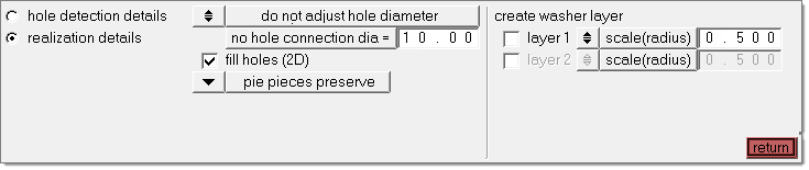
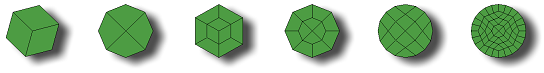
Fills detected holes during bolt realization. There are various quad patterns available, which cause a remeshing of the area around the hole. The picture below illustrates the available patterns.
Holes can also be filled with pie pieces. If the number of pie pieces is defined, the surrounding mesh is remeshed. The pie pieces preserve option also creates pie pieces, but takes the existing hole nodes into account and prevents the remeshing.
| Note: | Activating the fill holes (2D) option deactivates the no. of nodes around hole option. |
|
| • | no. of nodes around hole |
|
There are 4 different options available:
|
|
Uses the number of nodes of the appropriate origin hole. This is the default option and prevents the surrounding mesh from being remeshed. For new holes, the auto option is used.
|
|
Specify the exact number of nodes (default is 8). The surrounding mesh gets remeshed.
|
|
Specify an element size (default is 5.0). The number of elements around the hole is calculated based on this size. This is the preferred option for extremely different hole diameters. The surrounding mesh gets remeshed.
|
|
Performs a node distribution based on the underlying mesh size. The number of nodes is always rounded to an equal number.
|
Create Washer Layer:
For 2D holes, one or two washer layers can be created, after which the surrounding mesh gets remeshed.
The width of the washer can be defined:
| • | By factoring the hole radius. |
| • | By directly specifying the exact width. |
|
See Also:
Connector Panels
connectors module


