In this tutorial you will learn how to generate a hexcore mesh with a boundary layer. Included are the following steps:
| • | Boundary layer generation |
| • | Generation of the hexcore mesh, pyramid elements and the tetra mesh |
| • | Preparation of the model for the export |
The model file used in this exercise can be found in the es.zip file. Copy the file(s) from this directory to your working directory.
| 1. | From the menu bar, select Preferences > User Profiles or click  on the Standard toolbar. on the Standard toolbar. |
| 2. | Select Engineering Solutions > CFD > AcuSolve. |
|
| 1. | Click the Open Model icon  on the Standard toolbar. on the Standard toolbar. |
| 2. | Select the ujoint_cfd.hm file. |
| 3. | Click Open to load the file. |
|
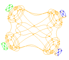
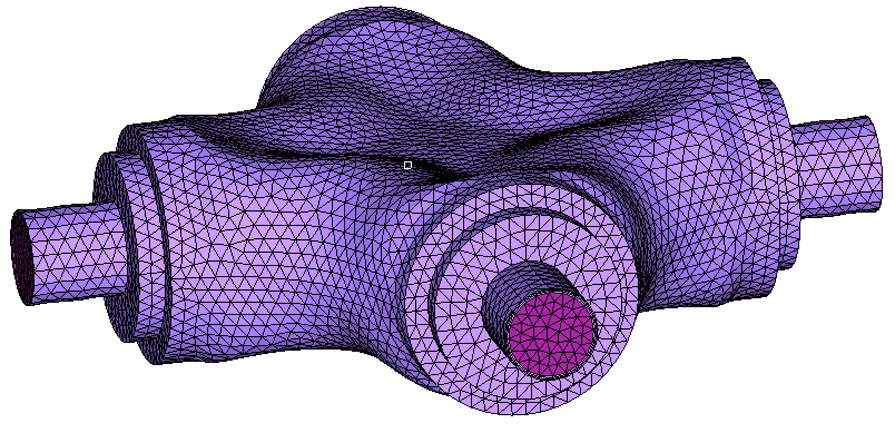
| 1. | In the Model browser, expand Component, right-click on it and select Show. |
| 2. | Click Mesh > Surface Mesh 2D > Automesh. |
| 3. | Click the size and bias subpanel. |
| 4. | Set the element size = field to 5.0. |
| 5. | Set the mesh type to trias. |
| 6. | Ensure that both the size and skew checkboxes are activated. |
| 7. | Ensure toggles are set to elems to surf comp and first order. |
| 8. | Click surfs and selected all. |
| 9. | Click mesh. A message on the status bar indicates the number of elements created. |
| 10. | Double-click return to close the panels. |
|
| 1. | Click Mesh > Volume Mesh 3D > Hex-core. |
| 2. | Enter the parameters as shown in the image below: |
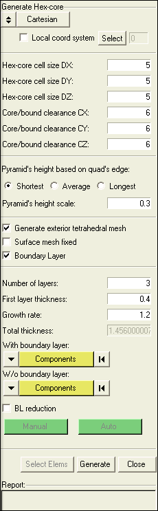
| 3. | Checking the box for Generate exterior tetrahedral mesh and Boundary Layer makes the bottom part of the tab editable. Enter the Number of layers as three, the First layer thickness as 0.4 and the Growth rate as 1.2. |
| 4. | Under the header With boundary layer, click Components and select the component wall. |
| 5. | Under the header W/o boundary layer, click Components and select inflow and outflow. |
| 6. | Click Generate just above the Report area. If a message appears, select Yes. After the meshing finishes, a message appears stating that additional components have been created. |
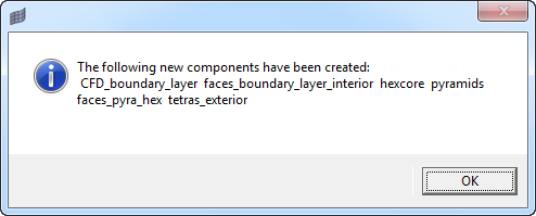
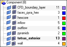
| 7. | Check the Model browser to see all the new components created. |
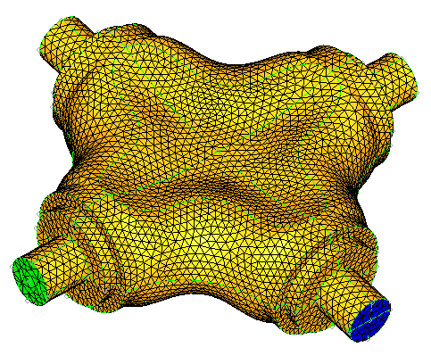
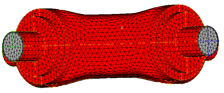
| 8. | Press F5 to open the Mask panel. While holding the shift key down, draw a box around roughly half of the model, and click mask. This will display the inside of the model. |
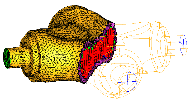
| 9. | Click return to close the panel. |
|
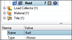
| 1. | In the Model browser, right-click Component and select Create. The Entity Editor opens. |
| 2. | For Name enter fluid. Leave the Type as None. |
| 3. | Right-click Component again select Show to remove the masking effect. |
| 4. | From the View menu, select Mask Browser. |
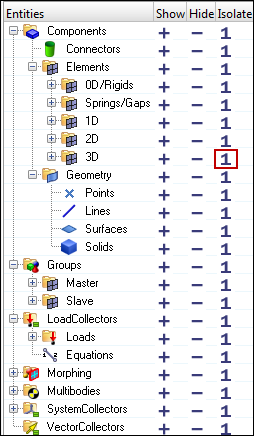
| 5. | Display only the volume elements by clicking the "1" in the row for 3D elements. |
| 7. | Click elems and select displayed. |
| 8. | Click dest component = and select the fluid component. |
| 9. | Click move, and then click return. |
| 10. | In the Mask browser, set only the 2D elements to display. |
| 11. | Click Mesh > Delete > Elements. Click elems and select displayed. |
| 12. | Click delete entity. This deletes all 2D elements from the model. |
| 13. | While still in the Delete panel, click the toggle and switch from elems to comps. Click comps and select the components that are now unused: |
| 14. | Click delete entity and click return. |
| 15. | In the Model browser, right-click Component and select Show to display the remaining components. Only volume elements are now available in the model. |
| 17. | Click comps and select the fluid component. |
| 18. | Enter the tolerance as 0.010 and select find faces. Click return to close the panel. |
| 20. | Click elems and select the elements on the inlet. |
| 21. | Click dest component = and select the inflow component. Click move. |
| 22. | Click elems again and select the elements on the outlet. |
| 23. | Click dest component = and select the outflow component. Click move. |
| 24. | Click elems again, select by collector and select ^faces. |
| 25. | In the dest component = field, select wall and click move. This will move the remaining elements in the ^faces component into the wall component. |
| 26. | In the Model browser, delete the ^faces component. |
| 27. | Display all the components and export the model to the CFD solver of your choice. |
|


