In this tutorial you will generate a wind tunnel type mesh for external CFD analysis. The mesh consists of a Cartesian hexa-mesh for the far field, and a hybrid grid (tetras with boundary layers) in the vicinity of the object.
The tutorial includes the following steps:
| • | Setting the user profile |
| • | Opening the model file to be used |
| • | Using the wind tunnel functionality |
| • | Volume meshing using the CFD Tetramesh panel |
| • | Organizing the model and preparation for CFD export |
| 1. | From the menu bar, select Preferences > User Profiles or click  on the Standard toolbar. on the Standard toolbar. |
| 2. | Select Engineering Solutions > CFD > AcuSolve. |
|
| 1. | From the Standard toolbar, click the Open Model icon  . . |
| 2. | Select the airplane.hm file. |
| 3. | Click Open to load the file. |
|
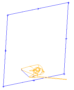
| 1. | Click Mesh > Volume Mesh 3D > Wind Tunnel. The Wind-Tunnel tab opens, displaying instructions for using this tool. |
| 2. | Enter values for your model as shown in the following image: |
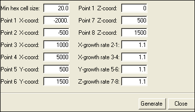
| 3. | Click Generate. A pop-up message will display the estimated number of hexahedral elements that will be created with the specified minimum hex cell size. |
| 4. | Click Yes on the pop-up message. The Wind Tunnel Mesh tool generates hexa, pyramids and shell elements and groups them into several collectors. |
You may need to rotate the model to obtain this view
|
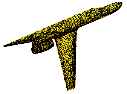
| 1. | In the Model browser, expand Component, right-click plane, and select Isolate. |
| 2. | Click Mesh > Surface Mesh 2D > Automesh. This automatically loads the surface deviation subpanel. |
| 3. | With surfs selected in the toggle, hold SHIFT and drag a box around the entire visible airplane geometry. You may need to resize the display first. |
| 4. | For element size =, enter 10. |
| 5. | For growth rate =, enter 1.2. |
| 6. | For min elem size =, enter 2. |
| 7. | For max deviation =, enter 0.1. |
| 8. | For max feature angle =, enter 15. |
| 9. | Set mesh type to trias. |
| 10. | Ensure toggles are set to elems to surf comp and first order. |
| 11. | Click mesh. A message on the status bar indicates the number of elements created. |
|
| 1. | In the Model browser, show the elements and geometry for box_sym. |
| 2. | In the Automesh panel, click the size and bias subpanel. |
| 3. | With the surfs toggle active, click any visible part of the box to select it. |
| 4. | For element size =, enter 20 and set the mesh type to trias. |
| 5. | For map, activate the checkboxes for size and skew. |
| 6. | Click mesh. The component is meshed. A message on the status bar indicates the number of elements created. |
| 7. | Double-click return to return to the main menu. |
|
| 1. | In the Model browser, right-click the component symp and select Show. |
| 2. | Click BCs > Check > Edge. |
| 3. | Click comps and select the components box_sym and symp. |
| 4. | For tolerance =, enter 0.1. |
| 5. | Click preview equiv. A message in the status bar indicates the number of nodes found. |
| 6. | Click equivalence. The nodes are equivalenced. |
| 7. | Click return to close the panel. |
|
| 1. | Click BCs > Components > Single. |
| 2. | In the Name field, enter box_ground. |
| 3. | Click Color and select magenta. |
| 4. | Click Create. The new collector has now been created. |
|
| 1. | In the Model browser, turn off the element display for symp and turn on the display for ground. |
| 2. | Click Mesh > Surface Mesh 2D > Surface/Mesh > Spline. |
| 3. | Set the selector toggle to nodes. |
| 4. | Click the nodes selector to open the extended entity selection menu and pick by path. |
| 5. | Set the second toggle to surface only. |
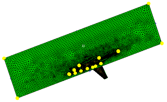
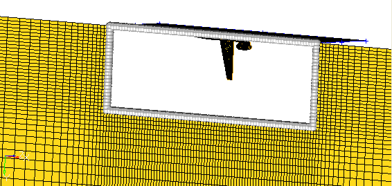
| 6. | Pick the nodes by path on the perimeter of the box bottom, as in the following image: |
| 9. | Click Mesh > Surface Mesh 2D > Automesh. |
| 10. | Select the size and bias subpanel, ensure the selector is set to surfs and the element size field is set to 20. |
| 11. | In the graphics area, click the box_ground surface. |
| 12. | Click mesh. A message on the status bar will indicate the number of elements created. |
| 13. | Double-click return to return to the main menu. |
|
| 1. | Click BCs > Check > Edge. |
| 2. | Click comps and select the components plane, box_sym, ground, trias_hexas_pyras, and box_ground. |
| 3. | Set the tolerance field to 0.1. |
| 7. | In the Model browser, turn off the display of ground, and turn on the element display of trias_hexas_pyras. |
| 8. | Return to the Edges panel. |
| 9. | Hold SHIFT and drag a box around all the visible components to select them all. |
| 10. | Click find edges. A message on the status bar indicates that no edges were found. |
| 11. | Select the components again and click preview equiv. A message on the status bar indicates that 0 nodes were found. This ensures that the volume is enclosed, which is necessary for the following tetra meshing step. |
|
| 1. | Click Mesh > Volume Mesh 3D > CFD tetramesh. |
| 2. | Under the With BL (fixed) header, click the comps selector and select the component plane. |
| 3. | Under the W/o BL (fixed) header, click the comps selector and select the components box_sym, box_ground and trias_hexas_pyras. |
| 4. | Click the BL parameters subpanel. |
| 5. | For Number of Layers = enter 3. |
| 6. | For First layer thickness = enter 0.7. |
| 7. | On the Tetramesh parameters subpanel, set the toggle to Interpolate. |
| 8. | Click mesh. The mesh may take a few minutes. When the mesh is complete, a message in the status bar will indicate the number of nodes and elements created. Note that two new components, CFD_tetcore001 and CFD_bl001, appear in the Model browser. |
|
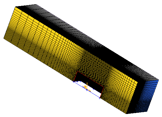
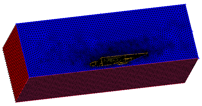
| 1. | Click Mesh > Check > Hidden Lines. In the panel, deactivate the clip boundary elements checkbox. |
| 2. | Click show plot and then check and then uncheck the xy plane, yz plane and xz plane checkboxes to display the model in different views. |
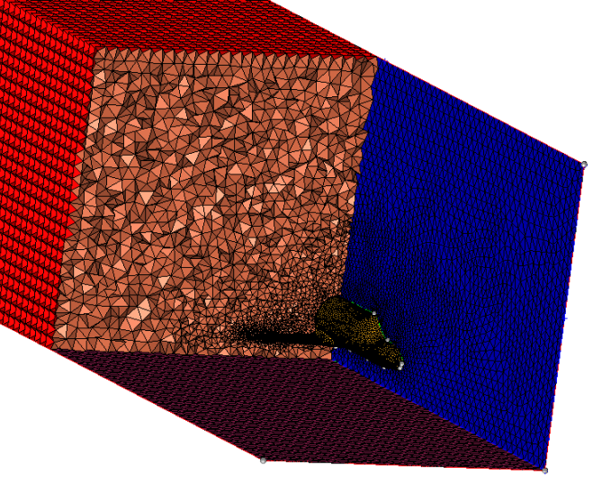
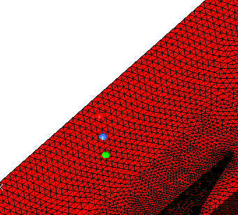
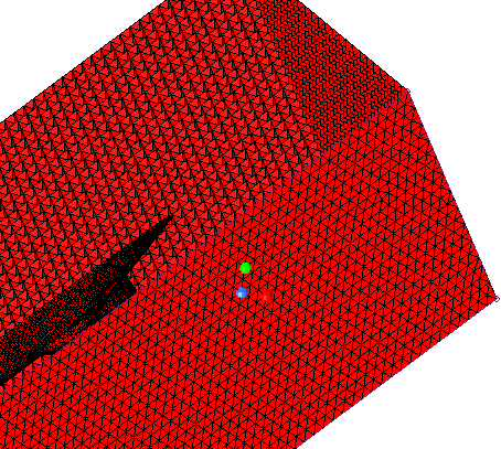
| 3. | Rotate and inspect the mesh from the side of the model. |
| 4. | Click and hold one of the corners of the model. While keeping the mouse button down, drag the corner of the model forth and back to sweep the cutting plane. |
|
| 1. | In the Model browser, turn off the display for plane, box_sym, trias_hexas_pyras and box_ground so that only CFD_tetcore001 and CFD_bl001 are visible. |
| 3. | Hold SHIFT and drag a box around the visible components to select them. |
| 4. | Click find faces. Note that a new component named ^faces appears in the Model browser. |
| 6. | In the Model browser, turn off the display of the elements of CFD_tetramesh_core and CFD_boundary_layer. |
| 8. | Click elems and select on plane. |
| 9. | Pick three nodes on the ^faces component, on the face that intersects the airplane model. A good way to determine which area to select is to isolate the display of the box_sym geometry. This will show you the face to focus on. Turn the display of the ^faces component back on, and select your three nodes. |
| 10. | Click select entities. |
| 11. | Click dest component = and select symp. |
| 13. | Click elems >> on plane. |
| 14. | Pick three nodes on the bottom of the ^faces component. A good way to determine which area to select is to isolate the display of the box_ground geometry. This will show you the face to focus on. Turn the display of the ^faces component back on, and select your three nodes. |
| 15. | Click select entities. |
| 16. | Click dest component = and select ground. |
| 18. | Click return to close the panel. |
|
| 1. | In the Model browser, right-click the component ^faces, and select Delete. |
| 2. | In the pop-up dialog, click Yes to confirm the deletion. |
| 3. | In the Model browser, turn on the display of CFD_tetcore001 and CFD_bl001. |
| 4. | Press the CTRL key and select edges_xz and edges_xy in the Model browser. |
| 5. | Right-click and select Delete. |
| 6. | In the pop-up dialog, click Yes to confirm the deletion. |
| 7. | In the same way, also delete trias_hexas_pyras, box_sym and box_ground. |
|
| 2. | Click elems and select by collector. |
| 3. | Select CFD_tetcore001 and CFD_bl001. |
| 5. | Click dest component = and select fluid_hex. |
| 6. | Click move. When the move is complete, nothing should be visible in the graphic area. |
|
| 1. | In the Model browser, display elements for fluid_hex. |
| 2. | Right-click fluid_hex in the Model browser and select Rename. |
| 3. | Enter the new name as fluid. |
| 4. | Select CFD_tetcore001 and CFD_bl001 and delete them using the process described in Step 14. |
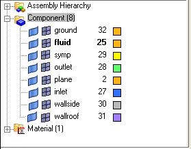
| 5. | Right-click Component and select Show to show all remaining components in the graphic area. |
|
| 1. | Click Export Solver Deck  . . |
| 2. | Ensure that CFD is selected for the File Type, and pick Fluent for the Solver Type. |
| 3. | Use the File field to navigate to the destination folder and enter the name wind_tunnel_mesh. |
| 4. | Click Export. A dialog appears. After reading the dialog, click Yes. |
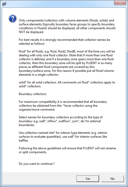
| 5. | In the pop-up dialog that appears, you are asked whether to reuse the setup from an existing FLUENT file. Since you just generated the grid and do not have a set up file (*.cas), click No. It may take a few minutes for the file to be created. |
| 6. | When the file creation is complete, a pop-up window appears. Click OK. |
|


