Engineering Solutions

CFD-1300: Plane 2D Meshing with Boundary Layers

CFD-1300: Plane 2D Meshing with Boundary Layers

Previous topic Next topic Expand/collapse all hidden text  

CFD-1300: Plane 2D Meshing with Boundary Layers

Previous topic Next topic JavaScript is required for expanding text JavaScript is required for the print function  

In this tutorial, you will learn to:

Generate 2D boundary layer type meshes with an arbitrary number of layers and thickness distribution in domains defined by edges.
Generate 2D boundary layer type meshes in areas where the clearance or separation of bounding edges is not enough to accommodate the user specified nominal boundary layer thickness / number or layers.

The model file used in this exercise can be found in the es.zip file. Copy the file(s) from this directory to your working directory.

hmtoggle_plus1greyStep 1: Load the CFD User Profile
1.From the menu bar, select Preferences > User Profiles or click userProfile-24on the Standard toolbar.  
2.Select Engineering Solutions > CFD > AcuSolve.        
3.Click OK.
hmtoggle_plus1greyStep 2: Open the Model File
1.Click the Open Model fileOpenModel-24 icon on the Standard toolbar.      
2.Select the manifold_inner_cylinder_2d.hm file.
3.Click Open to load the file containing the edges.
4.Inspect the edges elements that will be used to generate the volume mesh. The boundary mesh should only consist of PLOTEL (elem type) elements. You want to generate boundary layers on all the edges contained in the collectors called wall and inner wall.

HM_3260_01

hmtoggle_plus1greyStep 3: Check That All the Elements in Collectors Wall, Inner Wall, Inlet, and Outlets Define a Closed Loop (This Step is Optional)

Usually, this step is not necessary because the collectors containing edge elements (PLOTEL) are extracted from 2D surface meshes that naturally have free edges forming “closed” loops. However, there is a possibility that there may be duplicate nodes, and for this reason it is advisable to perform the following test:

1.Click BCs > Check > Edge.
2.Click comps.
3.Select the collectors wall, inner_wall, Inlet and Outlet.
4.Click select.
5.You need to ensure that the tolerance value is smaller than the minimum element length. To do this, first find the minimum element length. Click Mesh > Check > Elements > Check Elements.
6.Select 1-d.
7.Click length. A message indicates the minimum element length is 3.09, therefore you can safely use a tolerance of three.
8.Click return to close out of the current panel.
9.In the Edge panel, enter 3.0 in the tolerance = field and then click Preview Equiv. A message indicating that “0 nodes were found” will appear on the status bar.
hmtoggle_plus1greyStep 4: Generate a 2D BL Mesh
1.Click Mesh > Surface Mesh 2D > 2D Mesh with BL.
2.Click the 2D Native BL (planar) tab.

HM_3260_02

3.Set the default values to be assigned when adding collectors:
1st Layer Thickness  = 0.5
Growth Rate = 1.1 (This non-dimensional factor controls the change in layer thickness from one layer to the next)
Bound Type = Wall (Will generate a boundary layer mesh)
Number of boundary layers = 6 (value must be >= 0, as a zero value leads to no boundary layers even when Wall type is specified)
4.Uncheck the Retain node seeding on edge w/o BL option.
5.Click Add collector.
6.In the selector panel, click comps.
7.Select all four components.
8.Click select.
9.Click proceed.
10.In the 2D Boundary Layer Mesh window, all the selected components will be displayed in the Component list, as shown below:

HM_3260_03

11.Default values of boundary layer mesh (1st Layer Thickness, Growth Rate, and Bound Type) will be assigned to each component. To remove one or more components from the group, select those components from the list and click Remove.
12.In the 2D Boundary Layer Mesh window, set the Bound Type value for components Inlet and Outlet as In/Outlet.

The objective is to not generate boundary layers along the Inlet and Outlet components.

Note:Those elements may be remeshed based on the adjacent elements’ size.

HM_3260_04

13.Click Generate 2D BL Mesh to generate the mesh. When this task is finished, two collectors are automatically created: 2DBLMesh and 2DCoreMesh, as shown in the following image. Note that the quality of the mesh may not be very good, as described, following. In the next steps you will change some default parameters to allow boundary node insertion and movement.

hm3260_2

As indicated previously, components with Bound type In/Outlet will be remeshed based on the adjacent elements’ size. The two following figures illustrate the case where an inlet/outlet is defined with a single large element, after meshing the element size in this area has been reduced to obtain a smooth element size transition, leading to an excellent mesh quality.


    hm3260_3

hmtoggle_plus1greyStep 5: Changing Mesh Quality

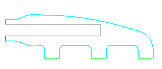
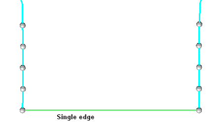
Often it may happen that boundary layer elements will have bad quality due to high aspect ratio. Such elements are created because of the large boundary edge length as shown in the following image.


hm3260_5


This problem can be resolved by limiting the maximum perimeter elements’ aspect ratio. The maximum boundary elements’ aspect ratio can be achieved using two approaches:

By addition of new nodes on the boundary / perimeter.
By node movement on the boundary / perimeter.
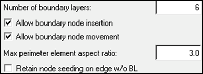
1.Activate the Allow boundary node insertion checkbox.

Refine the boundary edges by insertion of nodes on boundary edges. New node insertion is controlled by the specified maximum perimeter element aspect ratio.

Or

Activate the Allow boundary node movement checkbox.

This option is used to move boundary nodes along the original boundary. Boundary node movement is controlled by the specified maximum perimeter element aspect ratio.

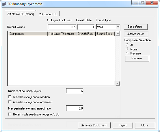
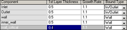
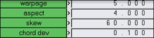
Enter the maximum perimeter element aspect ratio as shown in the following image:
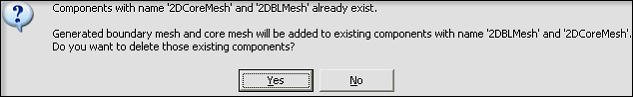
max_perimeter_element_aspect_ratio

2.Click Generate 2D BL Mesh to generate the mesh. If the model already contains collectors 2DBLMesh and 2DCoreMesh, then a pop-up message will ask you if you want to delete components 2DBLMesh and 2DCoreMesh before mesh creation or if you want to add newly created elements to the same collectors. Most of the time you will want to clear the existing mesh: click Yes. In some special cases you may want to keep them.

g2dblm_dialog

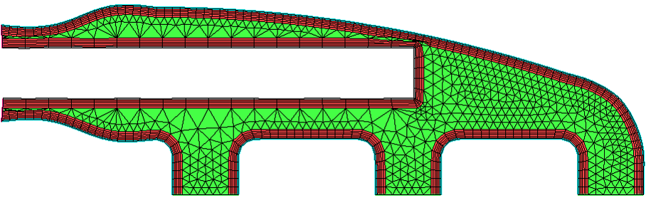
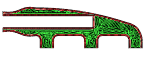
When this task is finished, two collectors 2DBLMesh and 2DCoreMesh are updated with new elements as shown in the following image:

hm3260_6

3.You can check the element’s aspect ratio by using the shortcut key F10 and selecting the 2-d page.

check_aspect_ratio


hm3260_7

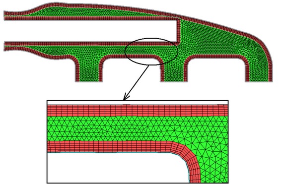
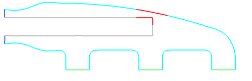
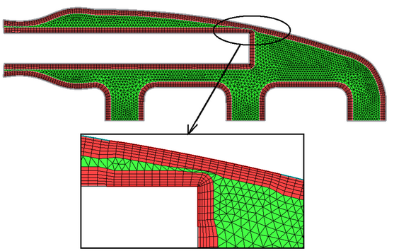
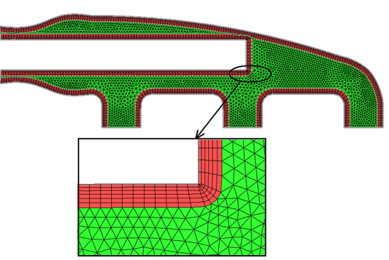
When the perimeter has sharp angles as shown in the following image, triangular elements are added to the boundary mesh to achieve a smoother transition of element sizes, and mesh smoothing also contributes to increase the mesh quality.

hm3260_8

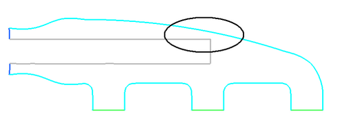
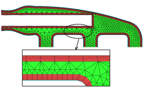
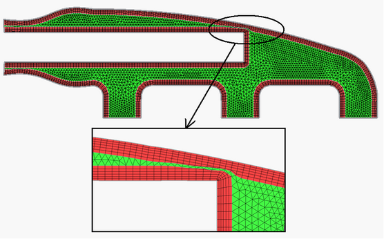
Also note that the automatic mesh generator performs a collision detection and avoids boundary layer interference by reducing the boundary layer thickness, as shown in the following inset:

hm3260_9

hmtoggle_plus1greyStep 6: Use a Distributed Boundary Layer Thickness to Generate a Boundary Layer and Core

The boundary layer type mesh generated in this tutorial was generated with uniform thickness. This is OK for a model like this manifold as long as the total boundary layer thickness does not lead to collision or interference that can occur when the sum of the BL thickness is close to or larger than the distance separating opposite walls. When such collision or interference occurs you have the following options:

Decrease the global boundary layer thickness (throughout / for all the BL edges).
Decrease locally the boundary layer thickness (BL edges around critical zones only).

Decrease locally the boundary layer thickness

1.In the 2D Boundary Layer Mesh window, click Reject to remove the created mesh. Collectors 2DBLMesh and 2DCoreMesh will be deleted.
2.Click Close to close the pop-up window.

Create new components (empty) to place the PLOTEL elements at critical zone (area where boundary layer elements may lead to collision)

3.Open the Model browser.
4.Click BCs > Components > Single.
5.Enter name as wall_critical.
6.Click Create and then Close.
7.Click BCs > Organize.
8.Select the boundary edges (PLOTEL) around the area where boundary layer elements may lead to collision. Refer to the following image for element selection.

hm3260_10

9.Set the dest group/dest component switch to dest component = and select the destination collector as wall_critical.
10. Click move to move the selected PLOTEL elements to the destination collector.

hm3260_11

11.Click Mesh > Surface Mesh 2D > 2D Mesh with BL.
12.In the 2D Native BL (planar) tab, click Add collector.
13.In the panel area, click comps.
14.Select the component wall_critical.
15.Click select.
16.Click proceed. The component wall_critical has been added to the component list.
17.Set 1st Layer Thickness of component wall_critical to 0.4.

component_list_wall_critical

18.Click Generate 2D BL Mesh to generate the mesh. When this task is finished, two collectors are automatically created: 2DBLMesh and 2DCoreMesh.
19.Now you can zoom in around component wall_critical and notice how boundary layer interference has been avoided by reducing the total boundary layer thickness as shown in the following image:

hm3260_12

hmtoggle_plus1greySummary

In this tutorial you generated 2D meshes with boundary layers on a complex cross section. You obtained a high quality mesh by allowing boundary node insertion and movement. Engineering Solutions automatically cuts back the number of layers when boundary layer collision occurs, thus producing a consistent mesh even in narrow areas. In narrow passages you can also reduce the total boundary layer thickness by starting with a smaller first layer thickness and/or a smaller growth rate.