To open the Contact browser, click View > Contact Browser from the menu bar. The Contact browser is only available in the Abaqus, Ansys, Nastran, and OptiStruct user profiles.
Use the Contact browser to create, review, and modify contact interfaces and surfaces in a model. Contact interfaces and surfaces can be imported, created manually, or generated automatically using the AutoContact option. Upon importing a solver deck or HyperMesh model, existing contacts are created and populated in the Contact browser. Contact interfaces and surfaces are organized into their respective folders in the browser.
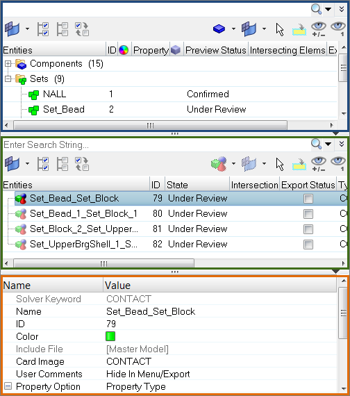
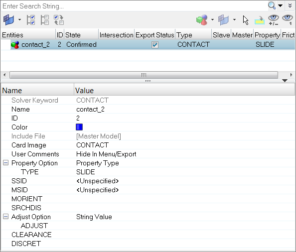
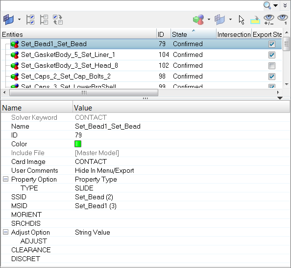
The Contact browser consists of three panes; the first pane displays the entities needed for contact definition, the second pane displays the contact information, and the third pane displays the Entity Editor.
|
In the Contact browser you can manually create contacts.
| 1. | In the first pane of the Contact browser, right-click and select Create from the context menu to create all of the entities needed for contact definition, such contact surfaces. |
| 2. | In the second pane of the Contact browser, right-click and select Create from the context menu to create contacts. The Entity Editor opens and displays the new contact. |
| Note: | The entities available in the context menu will vary depending on the user profile loaded. |
| 3. | Assign Master and Slave entities when creating contact pairs and contact ties. |
| 4. | Define additional entity parameters and properties accordingly. |
Contact browser and Entity Editor in the OptiStruct user profile
|
Auto contact generation works independent of whether the model is FE or geometric. When you elect to generate contacts automatically, contact bodies are detected and contact pairs and contact sets are created.
| 1. | In the Contact browser, right-click and select AutoContact from the context menu. The Create AutoContact dialog opens. |
| Tip: | To select all of the components in the model, right-click on the Components folder. |
| 2. | In the Pick application region field, select components to create contact interfaces and contact surfaces between. |
| Note: | You must select a minimum of two components. |
| 3. | Define contact parameters and properties accordingly. |
| a. | Select a Contact tolerance type. If Vicinity tolerance is selected, you must enter a vicinity tolerance value. |
| b. | Enter a Reverse angle limit. This determines the maximum curve angle to identify contacts. |
| c. | Enable Consolidate contact pair to group multiple isolated surfaces into one surface. |
| d. | Select a Contact type to specify the type of contact to be generated. Select Touch to generate “Contacts”, and Gap/Tie to generate “Tie”. |
| e. | Create and assign, or pick an existing property to attach to the contact pair. |
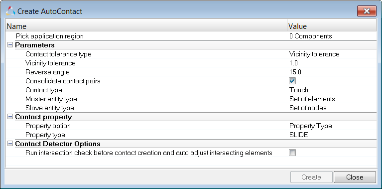
| 4. | Click Create. Based on a vicinity tolerance, the AutoContact tool searches throughout all of the selected components and automatically creates new Contact interfaces and contact surfaces between them. All the objects created are populated in the Contact browser into their respective folders. |
|
|
The Contact browser lists every contact interface and surface within a HyperMesh session and organizes them into their respective folders. You can modify these contact interfaces and surfaces using the Entity Editor.
| 1. | In the Contact browser, click the contact interface or surface to modify. The Entity Editor opens and displays the entities corresponding data. |
| Note: | If you select multiple entities in the browser, the Entity Editor displays the selected entities common corresponding data. The rows that contain ###, indicate that these fields do not contain common data, but can still be modified. When you modify the data, both common and ambiguous, HyperMesh applies the changes to all of the selected entities. To select multiple entities, left-click entities while pressing CTRL. |
| 2. | In the Entity Editor, modify the contact parameters and properties accordingly. Modifications are automatically applied throughout the model. |
|
| • | The Contact type Touch creates a contact pair, and the Contact type Gap/Tie creates a Tie contact. |
| • | Master ID and Slave ID types will be as per solver default Set of elements for master ID and Set of nodes for slave ID. |
| • | Auto contact will honor the entity type in Master and Slave entity type. |
| • | Master entity types have the following mutually exclusive options: Set of elements or SURF. Similarly Slave entity type will have Set of nodes, Set of elements, and SURF. You can only select one of the entities. |
| • | The Contact property option is only available when the Contact type is Touch. |
| • | You can assign Touch contacts a Property type (SLIDE, STICK, FREEZE), a Static Friction Coefficient, or an existing property (PCONT). |
|
| • | Creating and managing contact surfaces and pairs is handled by Contact browser. |
| • | Both manual contacts and AutoContact options are available. The AutoContact option can be used to create Surface to Surface contacts. |
| • | Before creating contact pairs in Engineering Solutions, it is recommend that you know which Ansys contacts are supported in Engineering Solutions. |
| • | Ansys contact regions are modeled like ordinary FE elements over the regions of FE models that represent the geometry. In Ansys terms, both CONTACT and TARGET surfaces are sets of elements at contact regions. Prior to Engineering Solutions 14.0.130, the Ansys interface supported the same principle as ANSYS, therefore both CONTACT and TARGET regions were elements over model geometry in Engineering Solutions. |
| • | Starting in Engineering Solutions 14.0.130, both contact and target regions are identified as CONTACT SURFACES. A pair of contact and target surfaces which interact with each other in analysis are GROUPS. You need to create contact surfaces for both CONTACT and TARGET regions. They will then be paired together under groups to successfully define the contacts. Ansys solver files (*.cdb files) with contacts are imported into Engineering Solutions, and identify the contact regions from the contact elements to show the regions as contact surfaces. Contact pairs can be seen in groups. |
| • | During export, Engineering Solutions creates contact elements from the contact regions and exports them as elements. In Ansys they are explained above elements with contact element type. |
| • | The Contact browser currently supports the creation of edge to edge, surface to surface, and point o surface contacts with pilot node and symmetry contact options. |
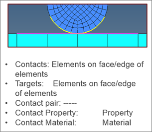
Engineering Solutions 14.0.120 and earlier
|
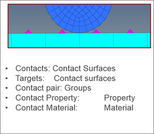
Engineering Solutions 14.0.130
|
|
| • | Automatically detect the contacts between selected parts. |
| • | Create different type of contacts (.MCT/.STI). |
| • | Modify the contacts already created: add/remove elements/nodes into the master/slave groups, change the type of the contacts (MCT to STI or STI to MCT). |
| • | Review the contacts in the model. |
|
|


