This exercise will help you learn how to define LS-DYNA airbags, loads, and contacts.
In this exercise, you will define an airbag, velocity, and contacts for a LS-DYNA analysis of a head impacting an inflating airbag.
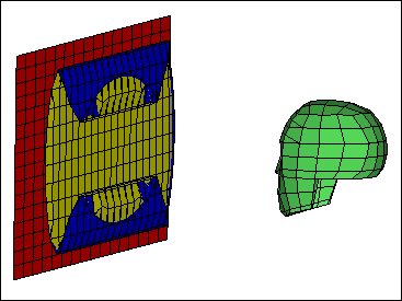
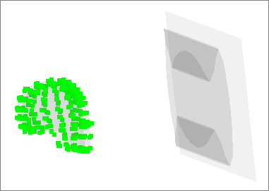
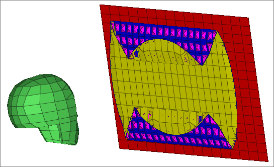
Head and airbag model
Step 1: Load the Engineering Solutions Crash LS-DYNA user profile
| 1. | From the Start menu, select Engineering Solutions > Crash > (HyperMesh). |
Step 2: Import the LS-DYNA model
| 1. | From the menu bar, select File > Import > Solver Deck. |
| 2. | In the File field, browse to the file airbag_start.key. |
Steps 3-5: Define *AIRBAG_WANG_NEFSKE for the airbag mesh geometry
Step 3: Create a set of parts, *SET_PART_LIST, containing the AirbagFront and AirbagRear components
| 1. | In the Model browser, right-click and select Create > Set from the context menu. A new set opens in the Entity Editor. |
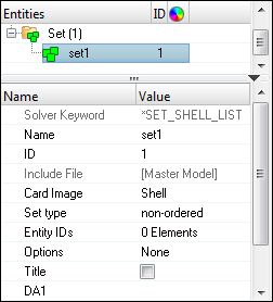
| 2. | For Name, enter airbag_set. |
| 3. | Set Card Image to Part. |
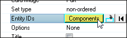
| 4. | For Entity IDs, click 0 Components >> Components. |
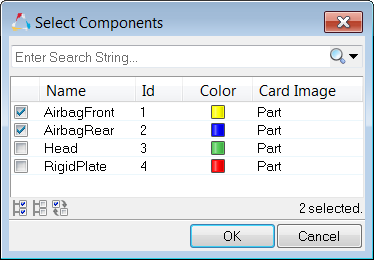
| 5. | In the Select Components dialog, select AirbagFront and AirbagRear, and then click OK. |
Step 4: Define the airbag (*AIRBAG_WANG_NEFSKE)
| 1. | Open the Solver browser by clicking View > Solver Browser from the menu bar. |
| 2. | In the Solver browser, right-click and select Create > *AIRBAG > *AIRBAG_WANG_NEFSKE from the context menu. A new control volume opens in the Entity Editor. |
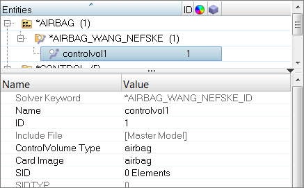
| 3. | For Name, enter airbag. |
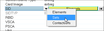
| 4. | Click SID. The entity selector becomes active. |
| 5. | Set the entity selector to Sets. |
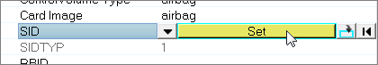
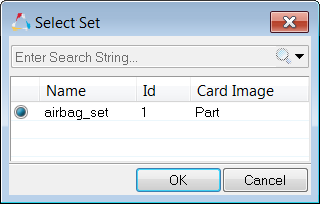
| 7. | In the Select Set dialog, select airbag_set and then click OK. |
| Note: | The parts in this set define the airbag's geometry. |
| 8. | For CV (Heat capacity at constant volume), enter 1023.0. |
| 9. | For CP (Heat capacity at constant pressure), enter 1320.0. |
| 10. | For T (Temperature of input gas), enter 780.0. |
| 11. | Click LCMT (Load curve specifying input mass flow rate) >> Curve. |
| 12. | In the Select Curve dialog, select airbag LCMT curve and then click OK. |
| 13. | For C23 (Vent orifice coefficient), enter 1.0. |
| 14. | Click LCA23 (Load curve defining vent orifice area as a function of pressure) >> Curve. |
| 15. | In the Select Curve dialog, select airbag LCA23 curve and then click OK. |
| 16. | For CP23 (Orifice coefficient for leakage), enter 1.0. |
| 17. | For PE (Ambient pressure), enter 1.0E-4. |
| 18. | For RO (Ambient density), enter 1.0E-9. |
| 19. | For GC (Gravitational conversion constant), enter 1.0. |
Step 5: Define an initial velocity of 3 mm/ms in the negative x-direction for the head with *INITIAL_VELOCITY_GENERATION
| 1. | In the Model browser, right-click and select Create > Load Collector from the context menu. A new load collector opens in the Entity Editor. |
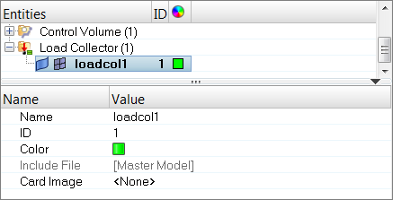
| 2. | For Name, enter velocity. |
| 3. | Set Card Image to InitialVel. |
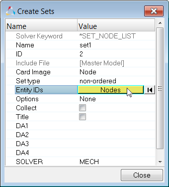
| 4. | Under Options, right-click on NSID and select Create from the context menu. The Create Sets dialog opens. |
| 5. | For Entity IDs, click 0 Nodes >> Nodes. |
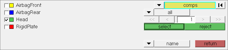
| 6. | In the panel area, click nodes >> by Collector. |
| 7. | Select the component, Head. |
| 10. | In the Create Sets dialog, click Close. |
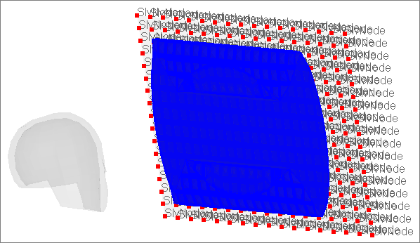
| 11. | In the Solver browser, *INITIAL > *INITIAL_VELOCITY folder, right-click on velocity and select Review from the context menu. Engineering Solutions highlights the load collector and grays out all of the other entities. |
| 12. | Return all of the entities to their original display color by righting-click on velocity and selecting Reset Review from the context menu. |
Steps 6-12: Define a contact between the airbag and head with *CONTACT_AUTOMATIC_SURFACE_TO_SURFACE
Step 6: Create a HyperMesh group with the card image SurfaceToSurface
| 1. | In the Solver browser, right-click and select Create > *CONTACT > *CONTACT_AUTOMATIC_SURFACE_TO_SURFACE > *CONTACT_AUTOMATIC_SURFACE_TO_SURFACE from the context menu. A new group opens in the Entity Editor. |
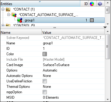
| 2. | For Name, enter Airbag_Head. |
Step 7: Specify the head to be the master surface with surface type 3, part ID
In this step, the Entity Editor should still be open for the Airbag_Head group.
| 2. | Set the entity selector to Components. |
| 4. | In the Select Components dialog, select Head and then click OK. |
Step 8: Specify all of the airbag to be the slave surface with surface type 2, part set ID
In this step, the Entity Editor should still be open for the Airbag_Head group.
| 2. | Set the entity selector to Set. |
| 4. | In the Select Set dialog, select airbag_set and then click OK. |
| Note: | This set contains the components, AirbagFront and AirbagRear. |
Step 9: View the master and slave entities
In this step, the Airbag_Head group should still be selected in the Solver browser.
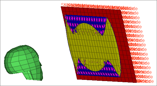
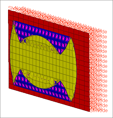
| 1. | In the Solver browser, right-click on Airbag_Head and select Review from the context menu. Engineering Solutions temporarily displays the master and slave entities blue and red, respectively. All of the other entities are temporarily displayed gray. |
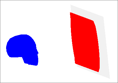
| 2. | Return all of the entities to their original display color by right-clicking on Airbag_Head and selecting Reset Review from the context menu. |
Step 10: Define *CONTACT_AIRBAG_SINGLE_SURFACE for the airbag
| 1. | In the Solver browser, right-click and select Create > *CONTACT > *CONTACT_AIRBAG_SINGLE_SURFACE from the context menu. A new group opens in the Entity Editor. |
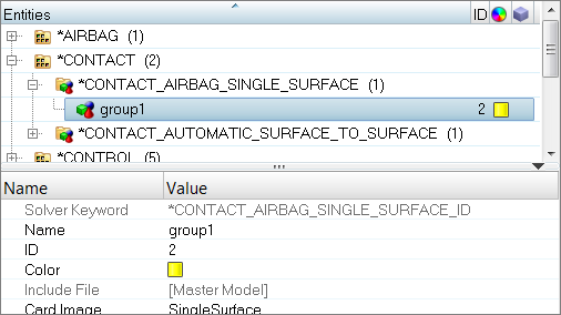
| 2. | For Name, enter airbag. |
Step 11: Define all of the airbag to be the slave surface with slave set type 2, part set ID
In this step, the Entity Editor should still be open for the airbag group.
| 2. | Set the entity selector to Set. |
| 4. | In the Select Set dialog, select airbag_set and then click OK. |
Step 12: View the slave entities
In this step, the airbag group should still be selected in the Solver browser.
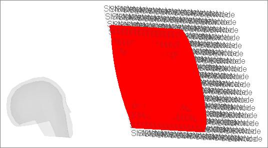
| 1. | In the Solver browser, right-click on airbag and select Review from the context menu. Engineering Solutions temporarily displays the master and slave entities blue and red, respectively. All of the other entities are temporarily displayed gray. |
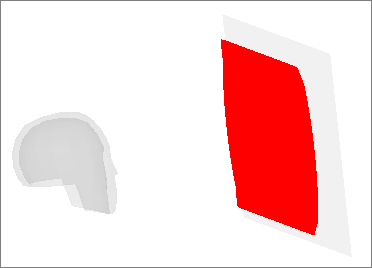
| 2. | Return all of the entities to their original display color by right-clicking on airbag and selecting Reset Review from the context menu. |
Steps 13- 18: Define a Contact Between the Plate and the Airbag with *CONTACT_NODES_TO_SURFACE
Step 13: Due to the dynamics of the contact, define the AirbagRear component to be the master surface with master type 0, set segment ID
| 1. | In the Solver browser, right-click and select Create > *SET > *SET_SEGMENT > *SET_SEGMENT from the context menu. A new contactsurf opens in the Entity Editor. |
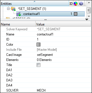
| 2. | For Name, enter AirbagRear_master. |
| 3. | Optional: Click the Color icon and select a color for the contactsurf. |
| 4. | For Elements, click 0 Elements >> Elements. |
| 5. | In the panel area, set the second switch to elems. |
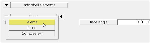
| 6. | Click elems >> by collector. |
| 7. | Select the component, AirbagRear. |
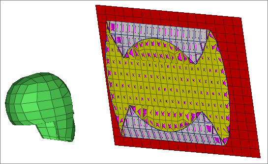
Step 14: Reverse the contactsurf’s pyramids so they point out of the airbag
| 1. | In the panel area, set the first switch to adjust normals. |
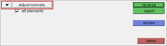
| 2. | Select the all elements checkbox. |
Step 15: Create *CONTACT_NODES_TO_SURFACE card
| 1. | In the Solver browser, right-click and select Create > *CONTACT > *CONTACT_NODES_TO_SURFACE > *CONTACT_NODES_TO_SURFACE from the context menu. A new group opens in the Entity Editor. |
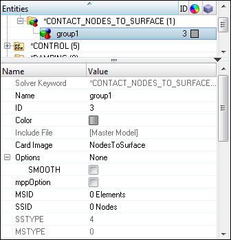
| 2. | For Name, enter Airbag_Plate. |
Step 16: Specify the AirbagRear_master contactsurf for the contact’s master surface
In this step, the Entity Editor should still be open for the Airbag_Plate group.
| 2. | Set the entity selector to Contactsurfs. |
| 4. | In the Select Contactsurfs dialog, select AirbagRear_master and then click OK. |
Step 17: Define the plate to be the contact’s slave surface with slave type 4, node set ID
| 1. | For SSID, click 0 Nodes >> Nodes. |
| 2. | In the panel area, set the switch to nodes. |
| 3. | Click nodes >> by collector. |
| 4. | Select the component, RigidPlate. |
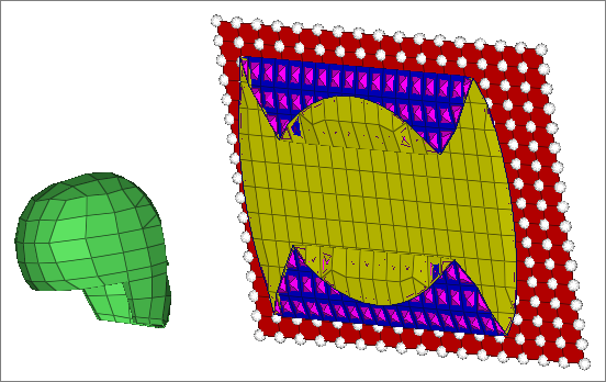
| 6. | Click add. Engineering Solutions adds the slave selection to the group Airbag_Plate. |
Step 18: View the master and slave entities
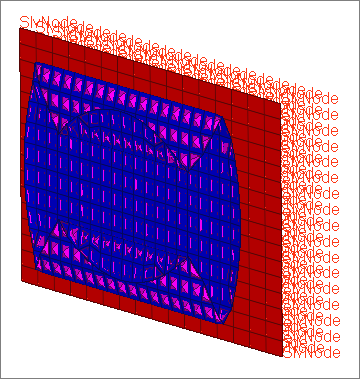
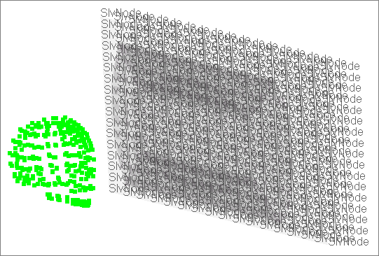
| 1. | In the Solver browser, *CONTACT > *CONTACT NODES TO SURFACE folder, right-click on Airbag_Plate and select Review from the context menu. The master and slave entities temporarily display blue and red, respectively. All of the other entities temporarily display gray. |
| 2. | Return all of the entities to their regular display color by right-clicking on Airbag_Plate and selecting Reset Review from the context menu. |
Step 19: Review the created solver entities using the Solver Browser
| 1. | In the Solver browser, *CONTACT > *CONTACT_AIRBAG_SINGLE_SURFACE folder, right-click on airbag and select Review from the context menu. The master and slave entities temporarily display blue and red, respectively. All of the other entities temporarily display gray. |
| Note: | Only slave (red) entities are shown because there are no master entities for this type of contact. |
| 2. | Return all of the entities to their regular display color by right-clicking on airbag and selecting Reset Review from the context menu. |
| 3. | In the Solver browser, *CONTACT > *CONTACT NODES TO SURFACE folder, right-click on Airbag_Plate and select Isolate Only from the context menu. Only the elements/components that are implicated in this contact display. |
| Tip: | If master and slave entities are not visible, make sure the Show/Isolate/IsolateOnly/Attached checkbox is selected in the Options tab of the Browser Configuration dialog. Access the Browser Configuration dialog by right-clicking in the Model browser and selecting Configure Browser from the context menu. |
| 4. | In the Solver browser, *CONTACT > *CONTACT_AIRBAG_SINGLE_SURFACE folder, right-click on airbag and select Show from the context menu. The entire airbag displays, as this entity contains the entire airbag. |
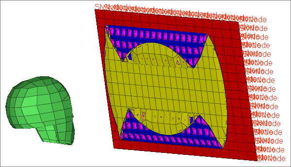
| 5. | In the *INITIAL > *INITIAL_VELOCITY folder, right-click on velocity and select Review from the context menu. The nodes on which velocity was applied displays. |
| 6. | Return all of the entities to their regular display color by right-clicking on velocity and selecting Reset Review from the context menu. |
Step 20: Export the model to an LS-DYNA 971 formatted input file
| 1. | From the menu bar, click File > Export > Solver Deck. The Export tab opens. |
| 2. | From the Template list, select Keyword971. |
| 3. | In the File field, navigate to your working directory and save the file as airbag_complete.key. |
| 4. | Next to Export options, click . . |
| 5. | From the Export list, select All. |
Step 21 (Optional): Submit the LS-DYNA input file to LS-DYNA 970
| 1. | From the Start menu, open the LS-DYNA Manager program. |
| 2. | From the solvers menu, select Start LS-DYNA analysis. |
| 3. | Load the file airbag_complete.key. |
| 4. | Click OK to start the analysis. |
Step 22 (Optional): View the results in HyperView
The exercise is complete. Save your work to a HyperMesh file.
|


