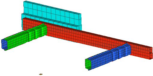
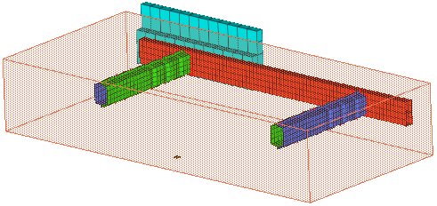
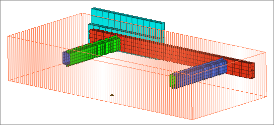
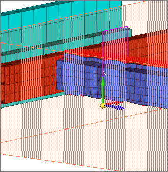
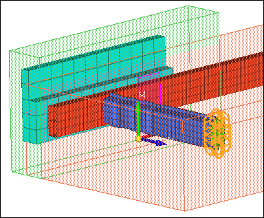
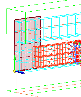
In this exercise, you will define model data, loads, constraints, a cross section, a rigid wall, and output for an LS-DYNA analysis of a bumper in a 40 percent frontal offset crash. The bumper model is shown in the image below.
Step 1: Load the Crash LS-DYNA user profile
| 1. | From the Start menu, select Engineering Solutions > Crash > (HyperMesh). |
| 2. | Select the LS-DYNA profile in Crash. |
Step 2: Import the LS-DYNA model bumper_start.key
| 1. | From the menu bar, click File > Import > Solver Deck. The Import tab opens. |
| 2. | In the File field, navigate to the file bumper_start.key. |
Step 3: Define *PART_INERTIA for the vehicle mass component to partially take into account the inertia properties and mass of the missing parts
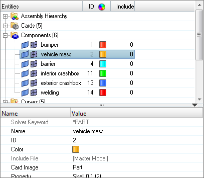
| 1. | In the Model browser, Component folder, click vehicle mass. The Entity Editor opens, and displays the component's corresponding data. |
| 2. | Set Options to Inertia. |
| 3. | For XC (X coordinate of center of mass), enter 700. |
| 4. | For YC (Y coordinate of center of mass), enter 0. |
| 5. | For ZC (Y coordinate of center of mass), enter 170. |
| 6. | For TM (translational mass), enter 800. |
| 7. | For IXX (XX component of target inertia), enter 1.5E+07. |
| 8. | For IXY (XY component of target inertia), enter -5.0E+03. |
| 9. | For IXZ (XZ component of target inertia), enter -8.0E+06. |
| 10. | For IYY (YY component of target inertia), enter 5.0E+07. |
| 11. | For IYZ (YZ component of target inertia), enter -900. |
| 12. | For IZZ (ZZ component of target inertia), enter 6.0E+07. |
| 13. | For VTX (Initial translational velocity of rigid body in x direction), enter -10. |
Step 4: Create a *DEFINE_BOX that contains all nodes except barrier nodes
| 1. | Open the Solver browser by clicking View > Solver Browser from the menu bar. |
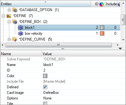
| 2. | In the Solver browser, right-click and select Create > *DEFINE > *DEFINE_BOX from the context menu. A new block opens in the Entity Editor. |
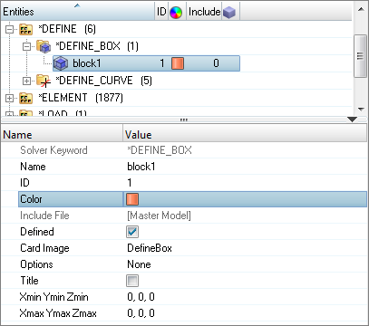
| 3. | For Name, enter box velocity. |
| 4. | Optional: Click the Color icon, and select a color for the block. |
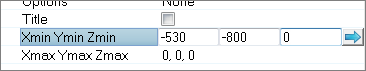
| 5. | For Xmin Ymin Zmin, enter -530, -800, 0. |
| 6. | For Xmax Ymax Zmax, enter 200, 800, 300. |
Step 5: Create initial velocity on all nodes except barrier nodes
A velocity boundary condition can also be created on a set of nodes by clicking  on the Collectors toolbar, and selecting Initialvel as the card image. on the Collectors toolbar, and selecting Initialvel as the card image.
| 1. | In the Solver browser, right-click and select Create > *INITIAL > *INITIAL_VELOCITY from the context menu. A new load collector opens in the Entity Editor. |
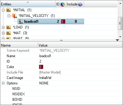
| 2. | For Name, enter velocity. |
| 3. | For VX (Initial velocity in the global X direction), enter –10. |
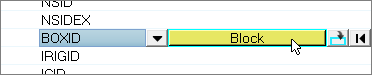
| 4. | Click BOXID, and then click Block. |
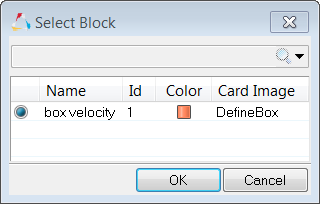
| 5. | In the Select Block dialog, select box velocity and then click OK. |
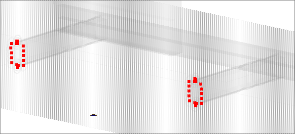
Step 6: View the closest nodes which are in the pre-defined node entity set (*SET_NODES_LIST) named Constrain Vehicle
Method 1
| 1. | In the Solver browser, *SET > *SET_NODE_LIST folder, right-click on Constrain Vehicle and select Review from the context menu. The set's nodes highlight. |
| 2. | Return all of the entities to their original display color by right-clicking on Constrain Vehicle and selecting Reset Review from the context menu. |
Method 2
| 1. | From the Setup page, click entity sets. |
| 2. | In the Entity Sets panel, click review. |
| 3. | Set the display RLs/hide RLs toggle to hide RLs. |
| Note: | This option filters all nodal rigid body sets from the list. |
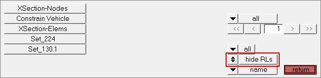
| 4. | Select the set, Constrain Vehicle. The set's nodes highlight. |
| 5. | Close the panel by clicking return. |
Step 7: Create *CONSTRAINED_EXTRA_NODES_SET
| 1. | In the Solver browser, right-click and select Create > *CONSTRAINED > *CONSTRAINED_EXTRA_NODES_SET from the context menu. A new constrained extra node opens in the Entity Editor. |
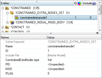
| 2. | For Name, enter ExtraNodes. |
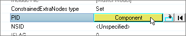
| 3. | For PID, click Unspecified >> Component. |
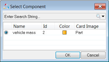
| 4. | In the Select Component dialog, select vehicle mass and then click OK. |
Step 8: Define the nodes in the Constrain Vehicle set to be a part of the vehicle mass rigid body
In this step, the Entity Editor should still be open for the ExtraNodes constrained extra node.
| 1. | For NSID, click Unspecified >> Set. |
| 2. | In the Select Set dialog, select Constrain Vehicle and then click OK. |
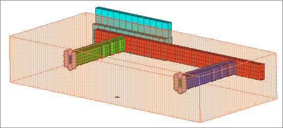
Step 9: View the extra nodes that are a part of the vehicle mass rigid body
| 1. | In the Solver browser, right-click on ExtraNodes and select Review from the context menu. The extra nodes temporarily display red, and PID (vehicle mass) displays blue. All of the other entities temporarily display gray. |
| 2. | Return all of the entities to their original display color by right-clicking on ExtraNodes and selecting Reset Review from the context menu. |
Step 10: Create an entity set, *SET_PART_LIST, for the vehicle mass component
All other components not in this set will be included in the contact.
| 1. | In the Solver browser, right-click and select Create > *SET > *SET_PART > *SET_PART_LIST from the context menu. A new set opens in the Entity Editor. |
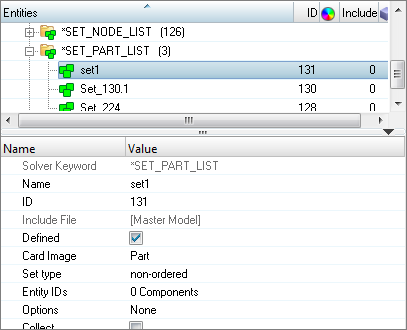
| 2. | For name, enter Exempt Parts. |
| 3. | For Entity IDs, click 0 Components >> Components. |
| 4. | In the Select Components dialog, select vehicle mass and then click OK. |
Step 11: Create *CONTACT_AUTOMATIC_GENERAL contact
| 1. | In the Solver browser, right-click and select Create > *CONTACT > *CONTACT_AUTOMATIC_GENERAL from the context menu. A new group opens in the Entity Editor. |
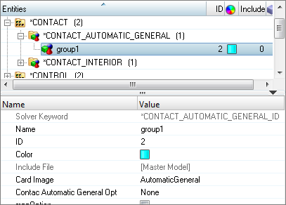
| 2. | For name, enter impact. |
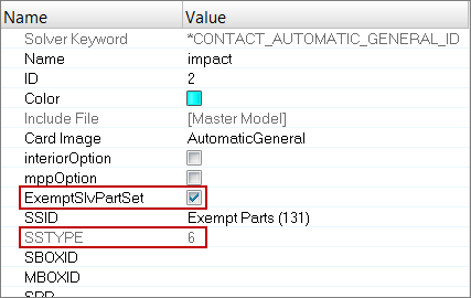
Step 12: Define the slave surface with slave set type 6, part set ID for exempted parts
In this step the Entity Editor should still be open for the impact group.
| 2. | Set the entity selector to Set. |
| 4. | In the Select Set dialog, select Exempt Parts and then click OK. |
| 5. | Select the ExemptSlvPartSet checkbox. The SSTYPE (slave surface type) value changes from 2 (part set ID) to 6 (part set ID for exempted parts). |
Step 13: Create an entity set, *SET_PART_LIST, to specify the elements that will contribute to the cross-sectional force results
| 1. | In the Solver browser, right-click and select Create > *SET > *SET_PART > *SET_PART_LIST from the context menu. A new set opens in the Entity Editor. |
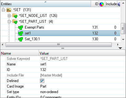
| 2. | For Name, enter XsectionPlane-Parts. |
| 3. | For Entity IDs, click 0 Components > Components. |
| 4. | In the Select Components dialog, select interior crashbox and exterior crashbox. |
Step 14: Define a section by creating *DATABASE_CROSS_SECTION_PLANE
| 1. | In the Solver browser, right-click and select Create > *DATABASE > *DATABASE_CROSS_SECTION_PLANE from the context menu. A new cross section opens in the Entity Editor. |
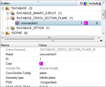
| 2. | For Name, enter Xsection_Plane. |
Step 15: Define the location and size of the section's plane
In this step the plane’s origin (the tail of the normal vector) is defined by a base node.
The Entity Editor should still be open for the Xsection_Plane cross section.
| 1. | Open the Create Nodes panel by clicking Geometry > Create > Nodes > XYZ from the menu bar, or by pressing F8. |
| 2. | In the x field, enter -320. |
| 3. | In the y field, enter -500. |
| 4. | In the z field, enter 100. |
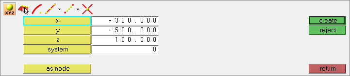
| 5. | Click create. A new node displays. |
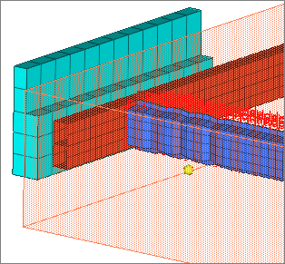
| 7. | In the Entity Editor, click XTAIL, YTAIL, ZTAIL (base node), and then click  . . |
| 8. | In the graphics area, select the base node you just created. |
| Tip: | If the base node is not visible, click  on the Visualization toolbar to display elements as a wireframe (skin only). on the Visualization toolbar to display elements as a wireframe (skin only). |
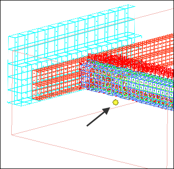
| 9. | Click proceed. The Entity Editor displays the coordinates of the base node in the XTAIL, YTAIL, ZTAIL field. |
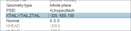
| 10. | Set Geometry type to Finite plane. |
| 11. | Click Normal, and then click . |
| 12. | In the panel area, set the orientation selector to x-axis. |
| 14. | Click Edge, and then click . |
| 15. | In the panel area, set the orientation selector to y-axis. |
| 16. | Click proceed. The Entity Editor displays the coordinates of the edge vector L in the Normal field. |
| 17. | For LENL (length of edge a, in the L direction), enter 100. |
| 18. | For LENM (length of edge b, in the M direction), enter 200. |
Step 16: Specify the parts slave to the rigid wall
In this step the Entity Editor should still be open for the Xsection_Plane cross section.
| 1. | For PSID, click Unspecified >> Set. |
| 2. | In the Select Set dialog, select XsectionPlane-Parts and then click OK. |
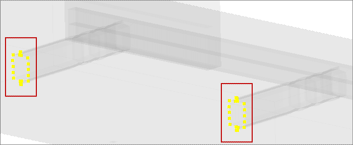
Step 17: View the entities slave to the rigid wall
| 1. | In the Solver browser, right-click on Xsection_Plane and select Review from the context menu. The slave entities and rigid wall highlight. All of the other entities temporarily display gray. |
| 2. | Return all of the entities to their original display color by right-clicking on Xsection_Plane and selecting Reset Review from the context menu. |
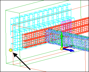
Step 18: Create a *DEFINE_BOX containing the nodes making up the barrier and bumper’s left side
These nodes will be slave to the rigid wall.
| 1. | In the Solver browser, right-click and select Create > *DEFINE > *DEFINE_BOX from the context menu. A new block opens in the Entity Editor. |
| 2. | For Name, enter half model. |
| 3. | Optional. Click the Color icon and select a color to display the block. |
| 4. | For Xmin Ymin Zmin, enter -600, -800, 0. |
| 5. | For Xmax Ymax Zmax, enter -460, 0, 400. |
Step 19: Define a HyperMesh group by creating *RIGIDWALL_PLANAR_FINITE
| 1. | In the Solver browser, right-click and select Create >*RIGIDWALL > *RIGIDWALL_PLANAR_FINITE from the context menu. A new group opens in the Entity Editor. |
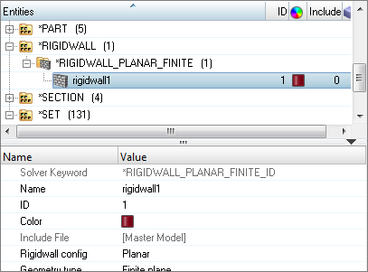
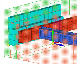
Step 20: Define the location and size of the rigid wall
In the Create Nodes panel, XYZ subpanel, the rigid wall’s origin (the tail of the normal vector) is defined by a base node. In this step, you will create a node from the create nodes panel and then select it for the base node.
In this step the Entity Editor should still be open for the wall group.
| 1. | Open the Create Nodes panel by pressing F8. |
| 2. | Go to the XYZ subpanel by clicking  . . |
| 3. | In the x field, ener -600. |
| 4. | In the y field, enter -750. |
| 5. | In the z field, enter 90. |
| 8. | In the Entity Editor, for Base node, click Unspecified >> Node. |
| 9. | In the graphics area, select the node you just created. |
| Tip: | If the base node is not visible, click on the Visualization toolbar to display elements as a wireframe (skin only). |
| 11. | Set Geometry type to Finite plane. |
| 12. | Click Normal, and then click . |
| 13. | In the panel area, set the orientation selector to x-axis. |
| 15. | Click Edge Vector L, and then click . |
| 16. | In the panel area, set the orientation selector to y-axis. |
| 18. | For Length X, enter 165. |
| 19. | For Length Y, enter 250. |
| Note: | The input values for Length X and Length Y are the length of the edges a and b in the L and M directions, respectively. These values define the extent of the wall. |
Step 21: Edit the card image for the rigid wall to specify the nodes in the *DEFINE_BOX half model as slave to the rigid wall
In this step the Entity Editor should still be open for the wall group.
| 2. | In the Select Block dialog, select half model and then click OK. |
| 3. | For Fric (Interface friction), enter 1.0. |
Step 22: Specify some nodes to be output to the ASCII NODOUT file with *DATABASE_HISTORY_NODE
| 1. | In the Solver browser, right-click and select Create > *DATABASE > *DATABASE_HISTORY_NODE from the context menu. A new output block opens in the Entity Editor. |
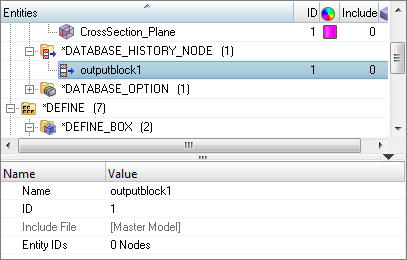
| 2. | For Name, enter nodeth. |
| 3. | For Entity IDs, click 0 Nodes >> Nodes. |
| 4. | In the graphics area, select a few nodes of interest. |
Step 23: Export the model to an LS-DYNA 970 formatted input file
| 1. | From the menu bar, click File > Export > Solver Deck. The Export tab opens. |
| 2. | Set File type to LsDyna. |
| 3. | In the File field, navigate to your working directory and save the file as Bumper_complete.key. |
Step 24 (Optional): Submit the LS-DYNA input file to LS-DYNA 970 solver
| 1. | From the Start menu, open the LS-DYNA Manager program. |
| 2. | From the solvers menu, select Start LS-DYNA analysis. |
| 3. | Load the file bumper_complete.key. |
| 4. | Click OK to start the analysis. |
Step 25 (Optional): View the results in HyperView
The exercise is complete. Save your work to a HyperMesh file.
|


