For this tutorial it is recommended to complete the introductory tutorial RD-3520: Pre-Processing for Pipes Impact Using RADIOSS for basic concepts on the RADIOSS interface.
In this tutorial you will learn how to set up a RADIOSS input deck for analysis of the impact of a bumper against a barrier behind a rigid wall. The modeling steps that are covered are:
| • | Associating /PART, with /MAT and /PROP. |
| • | Converting node-to-node connections (/RBODY) into a mesh-less welding formulation (/INTER/TYPE2 with /SPRING) using connectors. |
| • | Defining the contact for the elements in the bumper with an /INTER/TYPE7 card. |
| • | Defining the interaction between bumper and barrier with an /INTER/TYPE7 card. |
| • | Defining the interaction between barrier and rigid wall with the /RWALL/PLANE and /BOX/RECTA cards. |
| • | Specify the output of resultant forces for a plane on the left interior and exterior crash boxes with /SECT. |
| • | Creating a /TH/NODE card to output time history for nodes. |
The units used in the model are millisecond, millimeter and kilogram (ms, mm, kg), and the tutorial is based on RADIOSS Block 14.0.
The model used consists of a simplified bumper model (see image below):
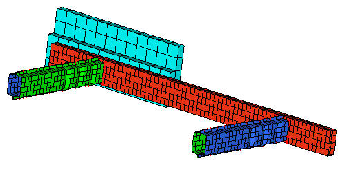
Bumper model
The model file used in this exercise can be found in the es.zip file. Copy the file(s) from this directory to your working directory.
| 1. | From the Start menu, select Engineering Solutions > Crash (HyperMesh) or click  on the Standard toolbar. on the Standard toolbar. |
| 2. | Select Crash and RADIOSS. |
|
| 1. | In the Standard toolbar, click the Open Model icon  and browse to select the bumper.hm file. and browse to select the bumper.hm file. |
| 2. | Click Open. The model loads into the graphics area. |
|
| 1. | In the Model browser, right-click and select Create > Component. The Entity Editor (EE) will open. |
| 2. | For Name, enter Vehicle mass. |
| 3. | Set Card Image to None and click Yes to confirm. |
| 4. | Click Geometry > Create > Nodes > XYZ to open the Nodes panel. |
| 5. | In the x field, enter 700. |
| 6. | In the y field, enter 0. |
| 7. | In the z field, enter 170. |
| 8. | Click create to create the node. |
| 9. | Go to the Setup page, and click rigids. |
| 10. | Click the selector arrow nodes 2-n: and select sets. |
| 11. | For primary node, select the node created in the steps above. |
| 12. | Click sets and select the Constrain Vehicle set. |
| 13. | With all the DOF’s checked, click create to create the rigid body. |
| Note: | A spider will be drawn connecting the created node to the edge nodes of the structure modeled. |
|
| 14. | Click the Card Edit icon  in the Collectors toolbar, set the selector to elements and select the rigid body created. in the Collectors toolbar, set the selector to elements and select the rigid body created. |
| 16. | Fill the mass and inertia information in the card image, as shown in the table below: |
Mass
|
JXX
|
JXY
|
JXZ
|
JYY
|
JYZ
|
JZZ
|
800
|
1.5E+07
|
-5.0E+03
|
-8.0E+06
|
5.0E+07
|
-900
|
6.0E+07
|
| 17. | Set ICOG as 4 and set Ispher as 0. |
| 18. | Click return to exit the panel. |
|
| 1. | Click View > Solver Browser to activate the Solver browser, if it is not active on your screen. |
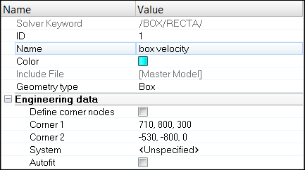
| 2. | In the Solver browser, right-click and select Create > BOX > BOX/RECTA. The Entity Editor opens. |
| 3. | For Name, enter box velocity. |
| 4. | Optionally, select a Color. |
| 5. | Enter Corner1 and Corner2 X, Y, and Z coordinates, as shown below. |
|
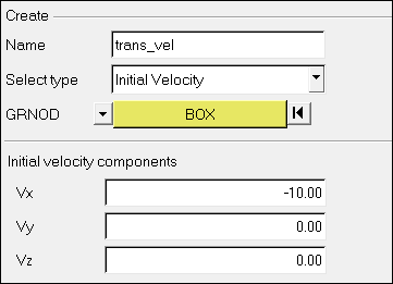
| 1. | Select BC's Manager from the Utility menu or click the BCs Manager icon  in the Crash toolbar. in the Crash toolbar. |
| 2. | In the BCs Manager, enter Name as tran_vel. |
| 3. | Select the Select type as Initial Velocity under the Create header. |
| 4. | Set the entity selector to BOX under GRNOD. |
| 5. | Click on it and select box velocity. |
| 6. | Enter -10, 0, 0 for Vx, Vy and Vz fields, respectively. |
| 7. | After the above step, a set named InitialVelocity_grnodbox is created automatically or you can create this set before the above step and then refer to this set in the above step, instead of BOX. |
| 8. | Click the Create > Close. |
|
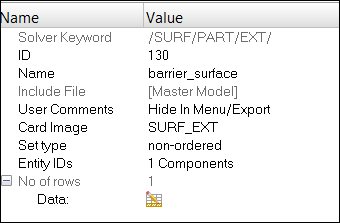
| 1. | In the Solver browser, right-click and select Create > SURF_EXT > PART. The Entity Editor opens. |
| 2. | For Name, enter barrier_surface. |
| 3. | For Entity IDs, click on Components. |
| 4. | In the Select Components dialog, select barrier and click OK. |
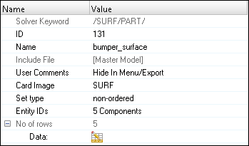
| 5. | In the Solver browser, right-click and select Create > SURF > PART. The Entity Editor opens. |
| 6. | For Name, enter bumper_surface. |
| 7. | For Entity IDs, click on Components. |
| 8. | In the Select Components dialog, select bumper, exterior crashbox left, exterior crashbox right, interior crashbox left, and interior crashbox right and click OK. |
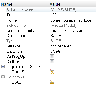
| 9. | In the Solver browser, right-click and select Create > SURF > SURF. The Entity Editor opens. |
| 10. | For Name, enter barrier_bumper_surface. |
| 11. | For Entity IDs, select Sets. |
| 12. | Click on Sets and select barrier_surface and bumper_surface and click OK. |
|
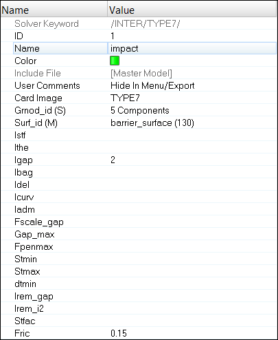
| 1. | In the Solver browser, right-click and select Create > INTER > TYPE7. The Entity Editor opens. |
| 2. | For Name, enter impact. |
| 3. | For Grnod_id (S) (slave entity), set the selector to Components. |
| 4. | Click Components, select bumper, interior crashbox (left and right) and exterior crashbox (left and right) and click OK. |
| 5. | For Surf_id (M) (master entity), set the selector to Set. |
| 6. | Click Set, select barrier_bumper_surface and click OK. |
| 8. | For the static coefficient Fric, enter 0.15. |
|
| 1. | Click the Display Numbers icon  on the Display toolbar. on the Display toolbar. |
| 2. | Click the node selector and select by ID. |
| 3. | For the IDs enter 6227, 6224, 5993. |
| 4. | Check the display checkbox on. |
| Note: | Node numbers will appear next to the node for selection in further steps. |
|
| 6. | From the Setup page, click systems. |
| 7. | Go to the create by node reference page. |
| 8. | Select Node ID 6224 for origin node. |
| 9. | Select Node ID 6227 for z axis. |
| 10. | Select Node ID 5993 for yz plane. |
| 11. | Click create to create a system. |
| 12. | Click the Card Edit icon on the Collectors toolbar. |
| 13. | Set the entity selector to systs. |
| 14. | Select the system and click edit. |
| 15. | Change the option from Skew to Frame. |
|
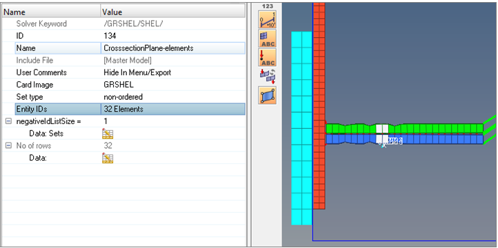
| 1. | In the Solver browser, right-click and select Create > GRSHEL > SHEL. The Entity Editor opens. |
| 2. | For Name, enter CrosssectionPlane-elements. |
| 3. | For Entity IDs, toggle to Elements selector active, select two rows of element on either side of the system, as shown in figure below. |
|
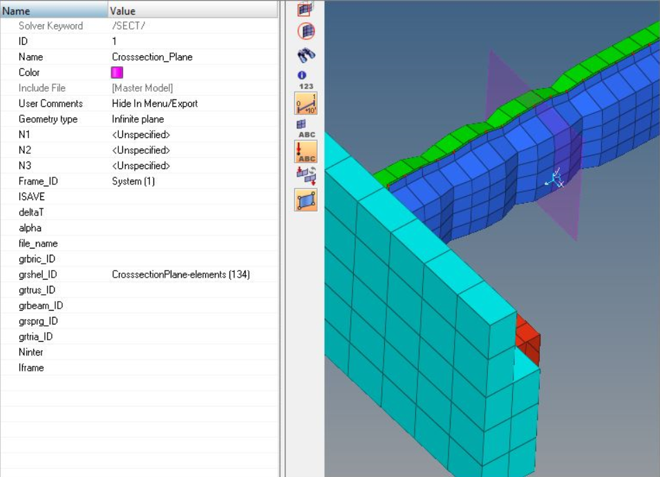
| 1. | In the Solver browser, right-click and select Create > SECT > SECT. |
| 2. | For Name, enter Crosssection_Plane. |
| 3. | For Frame_ID, select the system defined in the previous step by clicking on the screen. |
| 4. | For grshel_ID, select the set CrosssectionPlane-elements which is defined in previous step, as shown below. |
|
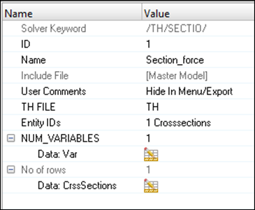
| 1. | Right-click in the Solver browser and select Create > TH > SECTIO. |
| 2. | For Name, enter Section_force. |
| 3. | For Entity IDs, toggle Crosssections and select Crosssection_Plane. |
| 4. | For NUM_VARIABLES, select 1 and for Data: Var, enter DEF. This selects the default output for RADIOSS. |
|
These nodes will be slave to the rigid wall.
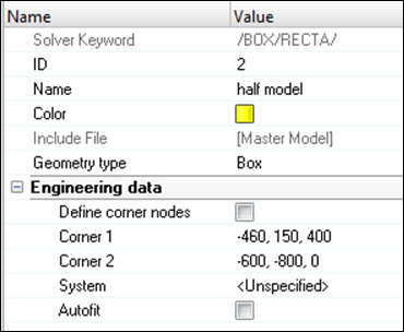
| 1. | In the Solver browser right-click and select Create > BOX > BOXRECTA. |
| 2. | For Name, enter half model. |
| 3. | Optionally, select a Color. |
| 4. | Enter Corner1 and Corner2 X, Y and Z coordinates, as shown below: |
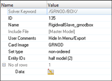
| 5. | Right-click in the Solver browser and select Create > GRNOD > BOX. |
| 6. | For Name, enter RigidwallSlave_grnodbox. |
| 7. | For Entity IDs, set the selector to Box and select the above created half model (BOX/RECTA). |
|
| 1. | Press the F8 key to enter the Create Nodes panel. |
| 2. | Select the XYZ ( ) subpanel. ) subpanel. |
| 3. | For x=, y= and z=, enter the values –600, -750 and 90, respectively. |
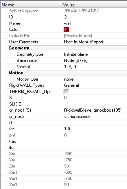
| 5. | In the Solver browser, right-click and select Create > RWALL > PLANE. |
| 7. | Set Geometry type as Infinite Plane. |
| 8. | With the Base node selector active, select the node that was created in step 4. |
| 10. | For grnod_id1 (S), toggle Set and select RigidWallSlave_grnodbox (GRNOD/BOX). |
| 11. | For fric, specify 1.0 for the friction coefficient. |
|
| 1. | Launch the Solver browser by clicking View > Solver Browser. |
| 2. | Right-click in the Solver browser general area to create the cards, shown below, with the given values for each parameter: |
Keyword Type
|
Keyword
|
Parameter
|
Parameter Value
|
CONTROL CARDS
|
TITLE
|
Status
|
[Checked]
|
CONTROL CARDS
|
TITLE
|
TITLE
|
Bumper_Impact
|
ENGINE KEYWORDS
|
RUN
|
Status
|
[Checked]
|
ENGINE KEYWORDS
|
RUN
|
Tstop
|
20
|
ENGINE KEYWORDS
|
PARITH
|
Status
|
[Checked]
|
ENGINE KEYWORDS
|
PARITH
|
Keyword2
|
ON
|
ENGINE KEYWORDS
|
PRINT
|
Status
|
[Checked]
|
ENGINE KEYWORDS
|
PRINT
|
N_Print
|
-1000
|
ENGINE KEYWORDS
|
TFILE
|
Status
|
[Checked]
|
ENGINE KEYWORDS
|
TFILE
|
Time Frequency
|
0.1
|
ENGINE KEYWORDS
|
ANIM/ELEM
|
Status
|
[Checked]
|
ENGINE KEYWORDS
|
ANIM/ELEM
|
EPSP
|
[Checked]
|
ENGINE KEYWORDS
|
ANIM/ELEM
|
VONM
|
[Checked]
|
ENGINE KEYWORDS
|
ANIM/BRICK/TENS
|
Status
|
[Checked]
|
ENGINE KEYWORDS
|
ANIM/BRICK/TENS
|
STRESS
|
[Checked]
|
ENGINE KEYWORDS
|
ANIM/BRICK/TENS
|
STRAIN
|
[Checked]
|
ENGINE KEYWORDS
|
ANIM/SHELL/TENS/STRESS
|
Status
|
[Checked]
|
ENGINE KEYWORDS
|
ANIM/SHELL/TENS/STRESS
|
MEMB
|
[Checked]
|
ENGINE KEYWORDS
|
ANIM/SHELL/TENS/STRAIN
|
Status
|
[Checked]
|
ENGINE KEYWORDS
|
ANIM/SHELL/TENS/STRAIN
|
MEMB
|
[Checked]
|
ENGINE KEYWORDS
|
ANIM/VECT
|
Status
|
[Checked]
|
ENGINE KEYWORDS
|
ANIM/VECT
|
DISP
|
[Checked]
|
ENGINE KEYWORDS
|
ANIM/VECT
|
VEL
|
[Checked]
|
ENGINE KEYWORDS
|
ANIM/DT
|
Status
|
[Checked]
|
ENGINE KEYWORDS
|
ANIM/DT
|
TStart
|
0
|
ENGINE KEYWORDS
|
ANIM/DT
|
Tfreq
|
1
|
ENGINE KEYWORDS
|
DT/NODA
|
Status
|
[Checked]
|
ENGINE KEYWORDS
|
DT/NODA
|
CST 0 – Tmin
|
3.6e-4
|
|
| 1. | Click File > Export or click the Export icon  . . |
| 2. | For File, click the folder icon and navigate to the destination directory where you want to run. |
| 3. | Enter the name as bumper_impact and click Save. |
| 4. | Click the downward-pointing arrows next to Export options to expand the panel. |
| 5. | Toggle Merge starter and engine file to export the engine file with the model file. |
| 6. | Click Export to export both model and engine file. |
|
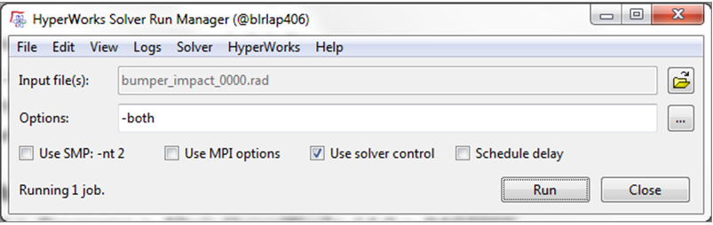
| 1. | Go to Start > Programs > Altair HyperWorks <version> RADIOSS. |
| 2. | For Input file, browse to the exercise folder and select the file bumper_impact_0000.rad. |
|
The exercise is complete. Save your work to a HyperMesh file.
|


