Step 1: Load the Engineering Solutions RADIOSS user profile
| 1. | From the Start menu, select Engineering Solutions > Crash (HyperMesh) or click  on the Standard toolbar. on the Standard toolbar. |
| 2. | Select Crash > RADIOSS. |
Step 2: Load the model file
| 1. | Click the Open Model icon  on the Standard toolbar. on the Standard toolbar. |
| 2. | In the Open Model dialog, navigate to the fullcar.hm file. |
| 3. | Click Open. The model loads into the graphics area. |
Step 3: Create and assign the material for the windshield components
| 1. | In the Model browser, right-click and select Create > Material. The Entity Editor is displayed below the Model browser. |
| 2. | For Name, enter windshield. |
| 3. | Set Card Image as M2_PLAS_JOHNS_ZERIL and click Yes to confirm. |
| 4. | Input the values, as shown below: |
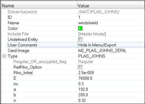
| 5. | In the Model browser, select components COMP-PSHELL_3 and COMP-PSHELL_16. |
| 6. | Click Mat_Id in the EE, select the material windshield and click OK to update the selected components with the created material. |
Step 4: Create and assign the material for the rubber components
| 1. | In the Model browser, right-click and select Create > Material. The Entity Editor is displayed. |
| 2. | For Name, enter rubber. |
| 3. | Set Card Image to M2_PLAS_JOHNS_ZERIL and click Yes to confirm. |
| 4. | Input the values, as shown below: |
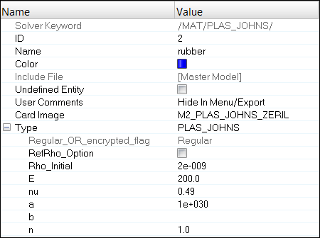
| 5. | In the Model browser, select components COMP-PSHELL_20 through COMP-PSHELL_23. |
| 6. | For Mat_Id, select the material rubber and click OK to update the selected components with the created material. |
Step 5: Create Steel material and assign to all other parts
| 1. | In the Model browser, right-click and select Create > Material. The Entity Editor is displayed. |
| 3. | Set Card Image to M2_PLAS_JOHNS_ZERIL. |
| 4. | Input the values, as shown below: |
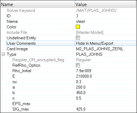
| 5. | In the Model browser select all components labeled with COMP-PSHELL and COMP-PROD, except COMP-PSHELL_3, COMP-PSHELL_16 and COMP-PSHELL_20 to COMP-PSHELL_23. |
| 6. | For Mat_Id, select the material steel and click OK to assign the material to the selected components. |
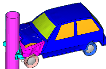
Step 6: Create a Rigid Wall
| 1. | In the Model browser, right-click and select Create > Rigid Wall. The Entity Editor is displayed. |
| 2. | For Name, enter ground. |
| 3. | Set Geometry type as Infinite plane. |
| 4. | Click Base node and select 'any node' from the model. |
| 5. | Define the normal vector Z = -1. |
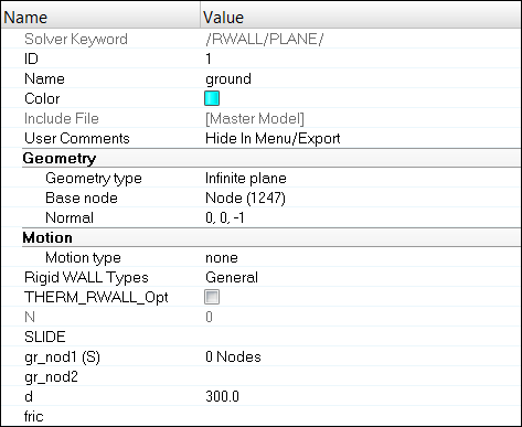
| 7. | Go to the Setup > Rigid Walls panel. |
| 9. | Click name and select Ground from the list. |
| 10. | Click the edit tab besides base node and change values of the coordinates as indicated below. |
X = -2300, Y = 1200, and Z = -1.
| 11. | Click update > return. |
Step 7: Create a Cylindrical Rigid Wall to represent Pole
| 1. | In the Model browser, right-click and select Create > Rigid Wall. The Entity Editor will display. |
| 3. | Set the Geometry type as Cylinder. |
| 4. | Click Base node and select ‘any node’ from the model. |
| 5. | Define the normal vector Z= 1. |
| 6. | For Radius node, do not select anything. Leave it as <Unspecified>. |
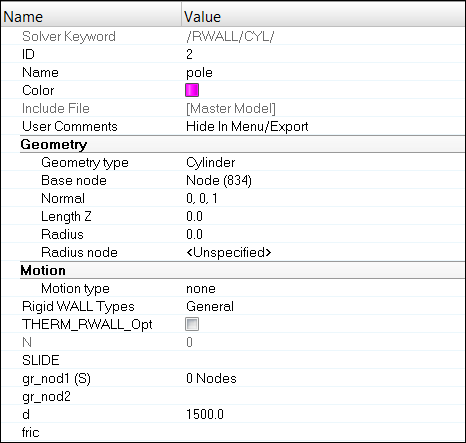
| 8. | Go to Setup > Rigid Walls panel. |
| 10. | Click name and select Pole from the list. |
| 11. | Click the edit tab besides base node and change values of the coordinates as indicated below. |
X = -320, Y = 1250, and Z = 0.
| 13. | Click update > return. |
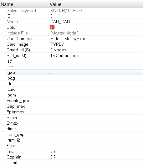
Step 8: Defining Contact using TYPE 7 interface (Self Contact)
| 1. | Hide all the 1D (TRUSSES) and 3D (SOLID) parts in the model by going to the Solver browser PROP > SHELL, Isolate only. Return to the Model browser. |
| 2. | From the Model browser, right-click and select Create > Contact. The Entity Editor will display. |
| 3. | For Name, enter CAR_CAR. |
| 4. | Set Card Image to TYPE7 and click Yes to confirm. |
| 5. | Set the option to Components for Surf_id (M) (master entity), and select displayed components and click OK. |
| 6. | Input other parameters as shown below. |
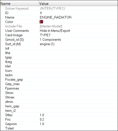
Step 9: Defining Contact using TYPE 7 interface between Engine and Radiator
| 1. | In the Solver browser, right-click and select Create > SURF_EXT > PART. |
| 2. | For Name, enter engine. |
| 3. | Click on Components and select COMP-PSOLID_24. |
| 4. | In the Model browser, right-click and select Create > Contact. |
| 5. | For Name, enter ENGINE_RADIATOR and set the Card Image as TYPE7 and click Yes to confirm. |
| 6. | For Grnod_id (S) (slave entity), set the selector switch to Components and click Components, select COMP-PSOLID_26. |
| 7. | For Surf_id (M) (master entity), set the selector switch to Set and click Set, select engine. |
| 8. | Input the values, as shown below: |
Step 10: Defining initial velocity
| 1. | From the Utility menu, click the BC's Manager or click the BCs Manager icon  in the Crash toolbar. in the Crash toolbar. |
| 2. | For Name, enter 35MPH, set the Select type field to Initial Velocity and set GRNOD to Parts. |
| 3. | Click comps and select all of the parts in the model. |
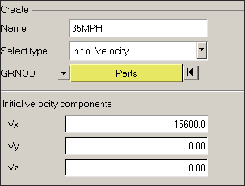
| 5. | Click Create to create the boundary condition and boundary condition appears in the table. |
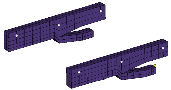
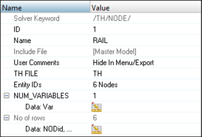
Step 11: Create Time History Nodes
| 1. | In the Model browser, isolate COMP-PSHELL_19. |
| 2. | Click Tools > Create Solver Cards > TH > NODE. |
| 3. | For Name, enter RAIL and select nodes on the Rail, as shown below. |
| 4. | For NUM_VARIABLES, select 1 and for Data: Var, enter the following: |
Step 12: Create output requests and control cards
| 1. | Launch the Solver browser by selecting View > Solver Browser. |
| 2. | Right-click in the Solver browser general area to create the cards shown below with the given values for each parameter: |
Keyword Type
|
Keyword
|
Parameter
|
Parameter Value
|
CONTROL CARDS
|
TITLE
|
Status
|
[Checked]
|
CONTROL CARDS
|
TITLE
|
TITLE
|
Car_Analysis
|
ENGINE KEYWORDS
|
RUN
|
Status
|
[Checked]
|
ENGINE KEYWORDS
|
RUN
|
Run Number
|
1
|
ENGINE KEYWORDS
|
RUN
|
Tstop
|
0.0601
|
ENGINE KEYWORDS
|
PRINT
|
Status
|
[Checked]
|
ENGINE KEYWORDS
|
PRINT
|
N_Print
|
-1000
|
ENGINE KEYWORDS
|
TFILE
|
Status
|
[Checked]
|
ENGINE KEYWORDS
|
TFILE
|
Time Frequency
|
9e-5
|
ENGINE KEYWORDS
|
ANIM/ELEM
|
Status
|
[Checked]
|
ENGINE KEYWORDS
|
ANIM/ELEM
|
EPSP
|
[Checked]
|
ENGINE KEYWORDS
|
ANIM/ELEM
|
VONM
|
[Checked]
|
ENGINE KEYWORDS
|
ANIM/ELEM
|
HOURG
|
[Checked]
|
ENGINE KEYWORDS
|
ANIM/VECT
|
Status
|
[Checked]
|
ENGINE KEYWORDS
|
ANIM/VECT
|
VEL
|
[Checked]
|
ENGINE KEYWORDS
|
ANIM/VECT
|
CONT
|
[Checked]
|
ENGINE KEYWORDS
|
ANIM/VECT
|
FOPT
|
[Checked]
|
ENGINE KEYWORDS
|
ANIM/DT
|
Status
|
[Checked]
|
ENGINE KEYWORDS
|
ANIM/DT
|
TStart
|
0
|
ENGINE KEYWORDS
|
ANIM/DT
|
Tfreq
|
0.003
|
Step 13: Export the model
| 1. | Click File > Export or click the Export icon  . . |
| 2. | Enter a filename in the destination directory where you want to run. |
| 3. | Enter the name FULLCAR and click Save. |
| 4. | Click the downward-pointing arrows next to Export options to expand the panel. |
| 5. | Click Merge starter and engine file to export the engine file with the model in one file. |
| 6. | Click Export to export both model and engine file. |
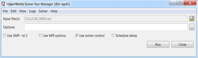
Step 14: Run the solver using RADIOSS Manager
| 1. | Go to Start > Programs > Altair HyperWorks <version> RADIOSS. |
| 2. | For Input file, browse to the exercise folder and select the file FULLCAR_0000.rad. |
Step 15 (Optional): View the Results in HyperView
The exercise is complete. Save your work to a HyperMesh file.
|