The goal of this tutorial is to see how head impact simulation following the pedestrian safety regulation EuroNCAP can be defined using the Pedestrian Impact tool starting from a full vehicle model. Pedestrian Impact automates the process with minimal input from you, therefore reducing the deck generation lead time with less human error.
The vehicle model used in this tutorial is based on the free Toyota Yaris model, provided by the National Crash Analysis Center (NCAC) (http://www.ncac.gwu.edu/vml/models.html). The original LS-DYNA model has been converted and validated with RADIOSS. The files needed for this tutorial are located in Toyota_YarisD_V2h_RADV12_000.rad in the es.zip file. Copy these files into a local directory before proceeding with this tutorial.
|
| 1. | From the Start menu, select Engineering Solutions > Crash (HyperMesh) or click  on the Standard toolbar. on the Standard toolbar. |
| 2. | Select Crash > RADIOSS. |
|
| 1. | Click Safety > Pedestrian Impact from the menu bar. |
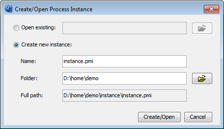
| 2. | Select a directory location for the instance.pmi file. This file allows you to save the ongoing process and retrieve it by opening a new HyperMesh/pedestrian impact session. |
| 3. | Select your local directory where the input data has been saved and click Create/Open. |
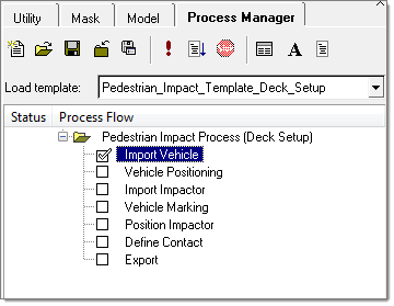
Invoking Pedestrian Impact opens a Process Manager tab that guides you through the process. You can go from one task to the next by clicking Next and Apply only on the input panel.
|
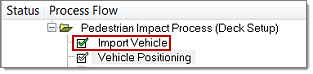
The first two steps of the pedestrian impact process consist of importing the vehicle model and trimming the vehicle.
| 1. | Import the vehicle model by selecting RADIOSS as the File type. |
| 2. | Select Toyota_YarisD_V2h_RADV12_v02_0000.rad for the Vehicle file. |

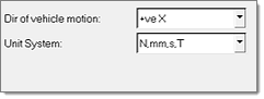
| 3. | Define the vehicle direction (+veX) and the model unit system (N,mm,s,T), as shown below, and click Import. |
| 4. | Click Yes when prompted to delete all of the existing models. |
For the pedestrian protection protocol only the front end of the vehicle participates. The trim functionality allows for cutting the full vehicle model and retaining only a selected portion. As a part of this process fixed boundary conditions are created at the boundary of the trimmed section. The trim process is optional.
| 5. | Define the Region to keep (Front) and the Trim Distance (2,000), as shown below. |
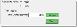
| 6. | Clicking Preview allows visualizing the portion of the vehicle that will be kept after the trimming operation. |
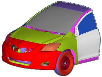
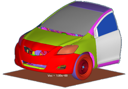
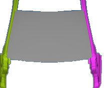
| 7. | Click Trim to activate the trimming operation. Once this operation is completed the vehicle model should look like the one shown in the image below. |
| 8. | This completes the import and trimming step. Click Next to open the Vehicle Positioning panel to complete the next step. |
| Note: | Once a step has been successfully completed, the check next to the panel name will turn green in color to indicate that it is completed. |
|
|
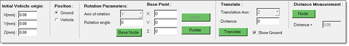
The Vehicle Positioning panel is used to define the vehicle and ground position. In this example, the vehicle position does not need to be changed. The ground level is at Z=0, therefore no translation of the ground is needed.
| 1. | Activate the Show Ground checkbox to toggle on the ground display. |
| 2. | Click Next to open the Import Impactor panel to complete the next step. |
|
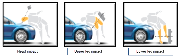
The Pedestrian Impact tool supports every pedestrian impact load case including head impact, upper leg impact and lower leg impact.
The Impactor Type you select in this step will determine the load case definition for the rest of the process.
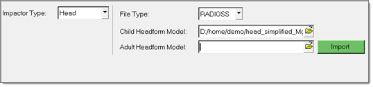
| 1. | Select Head as the Impactor Type. |
| 2. | Select RADIOSS as the File type. |
| 3. | Select head_simplified_Mgmms_0000.rad, as shown below, and click Import. |
| 4. | Click Next to open the Vehicle Marking panel to complete the next step. |
|
For the head impact load case, different types of regulations can be used to define the impact zone and target points:
| • | Global Technical Regulation (GTR No. 9) |
| • | European Regulation (ECE) |
| Note: | EuroNCAP protocols for head impact target point definitions are identical for versions 6.1, 7.0 and 8.0, and are supported in the Pedestrian Impact tool's vehicle marking process. |
|
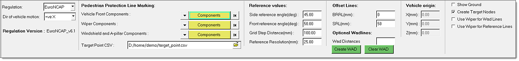
For each regulation, parameters used for the marking process are automatically defined.
| 1. | Select EuroNCAP for the regulation. |
| 2. | Select the Vehicle Front Components. |
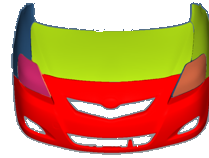
| 3. | Select the Windshield and A-pillar Components. |
| Note: | Wiper components are not modeled and can be ignored. |
|
| 4. | Specify the location where the .csv file used for the target point export has to be saved. |
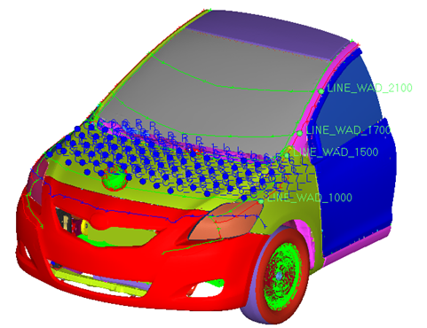
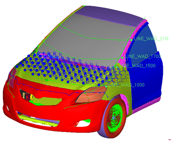
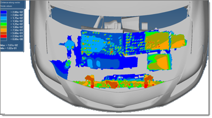
When the marking process is finished, grid points as well as impact zone lines are displayed on the vehicle.
| 6. | Click Next to open the Position Impactor panel to complete the next step. |
|
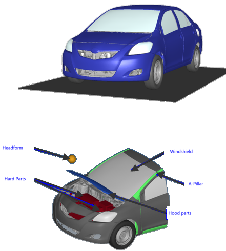
| 1. | In order to review the hard contact zones and detect critical impact zones, specify the Hood Components groups by selecting the hood parts and the Hard Components groups by selecting all engine block parts. |
| 2. | Click Draw to review the hard contact zones. |
| 3. | Click Add New Target to add new target points and select the nodes in the graphics area. Additional target points can also be defined by importing a .csv file containing target point information. |
| 4. | To export target points, select the impact points in the table that need to be exported. This option allows transferring target point definitions into CAD format that can be read back into HyperMesh. |
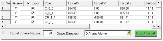
| 5. | Specify the Target Sphere Radius and Output Directory. |
| 6. | Click Export Target. The file ReferenceLinesAndTargetCollector.jt is created in the Output Directory specified. |
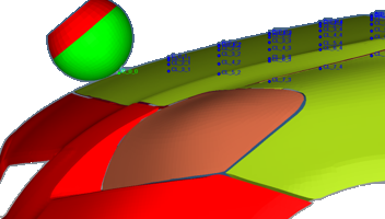
| 7. | To review the impactor position for specified target points, click on the Review radio button for the first point, C_0_0, for example. The impactor will be automatically positioned, as shown in the image below. |
| 8. | Click Apply to open the Define Contact panel to complete the next step. |
|
| 1. | Select Create New Contact for the Contact Method. |
| 2. | Activate the Use previously selected components for contact creation checkbox. |
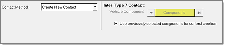
| 3. | Click Apply to automatically generate the contacts and open the Export panel. |
|
This tool exports input decks in a folder structure with different includes for the master model for the selected target points. A typical export directory of the tool is shown in the image below.
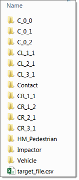
A folder is created for each target point selected. The name of the folder is based on the target location names (C_0_0 …). These folders contain:
| • | The master file for that location |
| • | An include file that contains the transformation card (allows you to move the impactor to the target point location). |
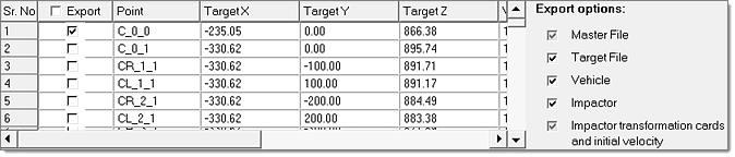
| 1. | Select the impact points that will be taken into account for the simulation. For this tutorial, you will select C_0_0. |
| 2. | Select the Export options, as shown below. |
| 3. | Define the solver control cards, as shown below. |
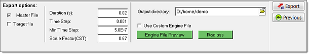
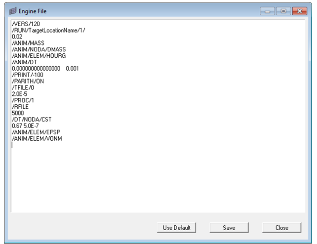
| 4. | Clicking Engine File Preview allows reviewing and editing the RADIOSS Engine file. Additional outputs can be defined in the dialog. Request output of plastic strain and Von Mises Stress, for example, by adding /ANIM/ELEM/EPSP and /ANIM/ELEM/VONM. |
| 5. | Click Save in the Engine File dialog. |
| Note: | It is recommended to run the Model Checker to verify the validity of the model. |
|
| 6. | Click Output > Checks > Model Checker. |
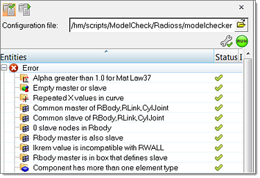
| 7. | If no errors are found, click Export to generate the RADIOSS input deck for the selected impact point. |
|
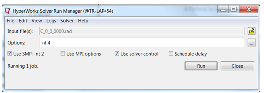
| 1. | Go to Start > Programs > Altair HyperWorks <version> RADIOSS. |
| 2. | For Input file, browse to the exercise folder and select the file C_0_0_0000.rad. It is recommended to control that the unit systems in the main input deck C_0_0_0000.rad are correctly defined. In this tutorial the unit system is Mg mm s. |
| 3. | Use the following parameters and start the simulation. |
|
See Also:
Pedestrian Impact


