Inside a mechanism bodies are connected together via kinematic joints. The different joints available are:
| • | Ball: Joint having the three translational degrees of freedom (DOF) blocked. This joint is defined by the center coordinates or by a node. |
| • | Cylinder: Joint allowing a translation and a rotation around the same axis. This joint is defined by the axis (Origin+direction given by coordinates or node selection). |
| • | Revolute: Same as Cylinder joint, without translation. |
| • | Slider: Same as Cylinder, without rotation. |
| • | Double Slider: A slider with a third body for which the motion is linked to the two main bodies via scale factors: |
| o | Motion_body3 = Factor1*Motion_body1 + Factor2*Motion_body2 |
| o | Where: 0<Factor1<1 and 0<Factor1<1 and Factor2=1-Factor1 |
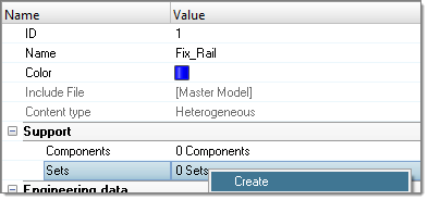
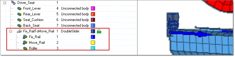
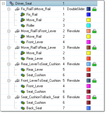
Create the Double Slider joint
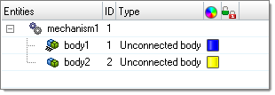
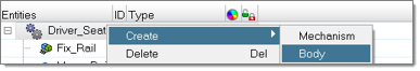
| 1. | In the Mechanism browser, select Fix_Rail and Move_Rail, and then right-click and select Connect. |
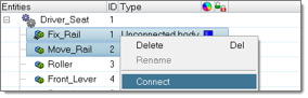
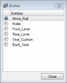
| Note: | Another way to connect bodies: Select Fix_Rail and then right-click and select Connect To. A dialog opens listing the available bodies. Select Move_Rail and close the dialog. |
|
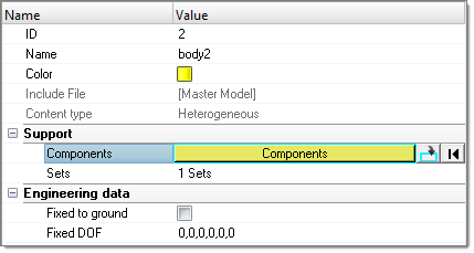
| 2. | Inside the joint Entity Editor select the Joint type DoubleSlider. |
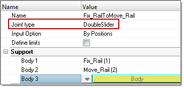
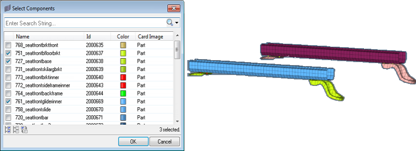
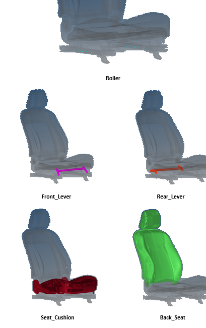
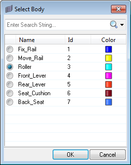
| 3. | Specify Body3 by selecting Roller inside the body list. |
| 4. | Verify that Input Option is set to By Positions. |
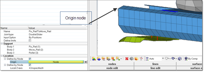
| 5. | Under Location, activate the two checkboxes labeled Define by Node. |
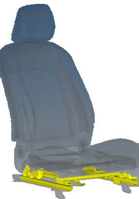
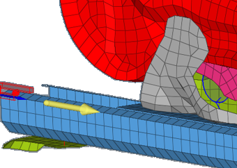
| 6. | Click Origin, select a node on the rail part and click proceed. |
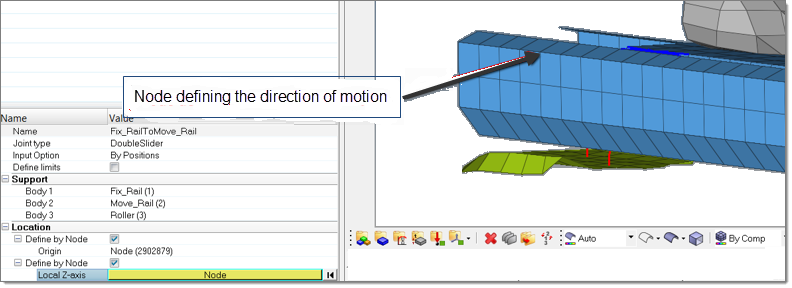
| 7. | Click Local Z-axis, select another node to define the direction of motion and click proceed. |
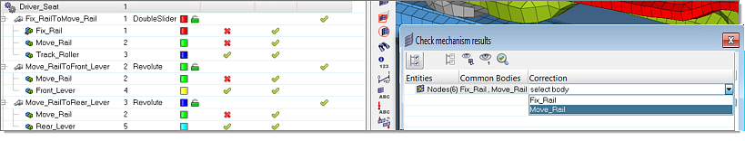
| 8. | Click Create to confirm the joint. The Double Slider joint is created in the Mechanism browser with the three bodies defined inside, as well as on the display. |
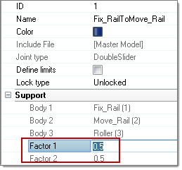
The scale factors (Factor 1 and Factor 2) defining the relative motion between Roller and Fix_Rail and Roller and Move_Rail are set up per default to 0.5.
| 9. | In order to change these values, select the DoubleSlider joint in the Mechanism browser and update the value of Factor 1 in the Entity Editor (Factor 2 is directly computed as 1-Factor 1). |
Define the joint limits
It is possible to define limits for each type of joint.
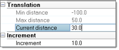
| 1. | For example, in the previous DoubleSlider Entity Editor, activate the checkbox Define limits, and provide the following limit values: |
Create the Revolute joints
All of the other joints are revolute joints and are defined in the same way – Origin + direction in Y-Axis.
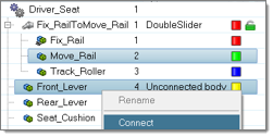
To create the revolute joint between Move_Rail and Front_Lever bodies perform the following steps.
| 1. | Select Move_Rail and Front_Lever, right-click and select Connect. |
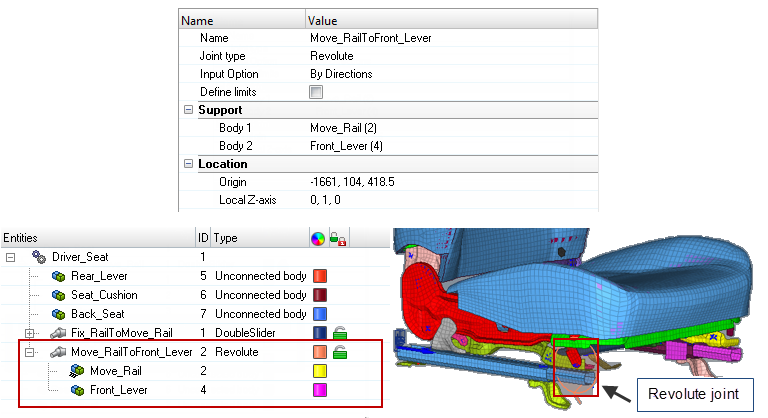
| 2. | In the joint Entity Editor, set Joint type to Revolute and Input Option to By Directions. |
| 3. | Click Origin and provide the coordinates of the axis-origin or define them by selecting a node. To do that, click the blue arrow, pick a node and click proceed. The following Origin coordinates should be used: -1661, 104 and 418.5. The Local Z-axis of the joint is oriented in the global y-axis: 0, 1, 0. |
| 4. | Click Create to confirm the creation of the revolute joint. |
| 5. | Repeat these steps to create the other revolute joints, defined as follow: |
Body 1
|
Body 2
|
Origin Coordinates
|
Local Z-axis
|
Move_Rail
|
Rear_Lever
|
-1961; 117; 408.5
|
0; 1; 0
|
Rear_Lever
|
Seat_Cushion
|
-2040.6; 104; 420.7
|
0; 1; 0
|
Front_Lever
|
Seat_Cushion
|
-1722.5; 121; 475
|
0; 1; 0
|
Seat_Cushion
|
Back_Seat
|
-2067; 103.6; 506
|
0; 1; 0
|
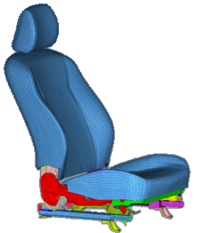
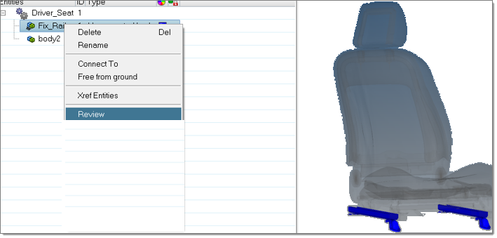
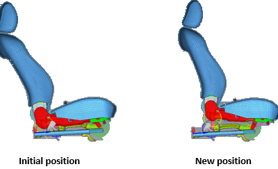
The complete seat mechanism should look like the image below.
|