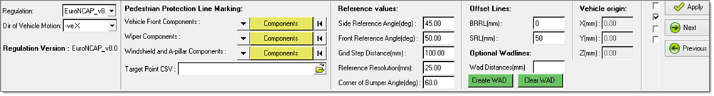
Regulation
|
Select EuroNCAP, Homologation or ECER.
|
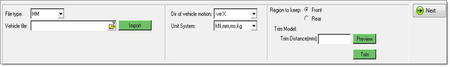
Dir of vehicle motion
|
Select -veX or +veX for the direction of vehicle motion.
|
Regulation Version
|
EuroNCAP versions 6.1, 7.0 and 8.0 are supported, Homologation version UN GTR No. 9 is supported and ECER version UN GTR No. 9 is supported.
|
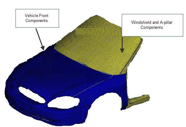
Vehicle Front Components
|
Select the vehicle front components. Components within the bumper and the bonnet rear reference line (BRRL) on the outer surface of the vehicle are considered as vehicle front components. This may include the bumper, hood, fenders, headlights and front grill, depending on the model.
|
Wiper Components
|
Select the wiper components. This is optional. All of the components between the bonnet and the windshield (for example plenum and cowl components) should be selected as wiper components.
|
Windshield and A-pillar Components
|
Select the windshield and A-pillar components. Required only for head impactors.
|
Target Point CSV
|
Use the file icon to browse for and select the .csv file. Required only for head impactors.
|
Side reference angle (deg)
|
The angle required to create the side reference line on selected components. The default value, per EuroNCAP, Homologation and ECER regulations, is set to 45 degrees. You can change the angle to between 35 and 55 degrees.
|
Front reference angle (deg)
|
The angle required to create the front reference line on selected components. The default value, per EuroNCAP, Homologation and ECER regulations, is set to 50 degrees. You can change the angle value to between 40 and 60 degrees.
|
Grid Step Distance (mm)
|
The distance between grid points. The default value, per EuroNCAP and Homologation regulations, is set to 100. The default value per ECER regulations is set to 165. You can change this for your requirements.
|
Reference Resolution (mm)
|
The distance used while interpolating reference line points. This should always be less than or equal to half of the grid step distance. The lesser its value the more time it takes to create the reference lines, but the lesser value results in better overlapping of geometry and reference lines.
|
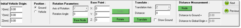
Vehicle origin
|
Add entries with changed vehicle origin coordinates after executing the vehicle positioning task. The changed vehicle coordinates are calculated automatically based on coordinates provided in the initial vehicle origin in the Vehicle Positioning panel. For marking the correct reference lines, WAD lines and grid points these entries are disabled.
|
BRRL (mm)
|
Specify the offset value for bonnet rear reference lines.
|
SRL (mm)
|
Specify the offset for side reference lines.
|
BRRL (mm)
|
The offset value required to create the BRRL offset line on selected components. You can change the offset value according to your requirements.
|
SRL (mm)
|
The offset value required to create the SRL offset line on selected components. You can change the offset value according to your requirements.
|
X (mm)
|
The X coordinate of vehicle origin is automatically calculated as per the vehicle movement in the positioning task.
|
Y (mm)
|
The Y coordinate of vehicle origin is automatically calculated as per the vehicle movement in the positioning task.
|
Z (mm)
|
The Z coordinate of vehicle origin is automatically calculated as per the vehicle movement in the positioning task.
|
Show Ground
|
Use the checkbox to show or hide ground.
|
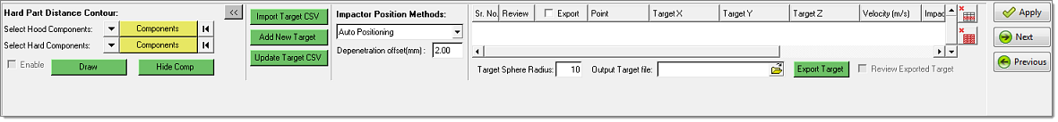
Create Target Nodes
|
Uncheck the checkbox if grid points should not be marked with head impactor.
|
Use Wiper for Wad Lines
|
Check the checkbox if wiper components selected should be taken into consideration for creating WAD lines.
|
Use Wiper for Reference Lines
|
Uncheck if wiper components selected should not be taken into consideration for creating reference lines.
|