|
»Click here to display Table of Contents«
|

FMVSS 201/ECE-R21 |

|

|

|

|
|
FMVSS 201/ECE-R21 |
|
|

|

|
|
»Click here to display Table of Contents«
|
FMVSS 201/ECE-R21 |
|
|
|
|
|
FMVSS 201/ECE-R21 |
|
|
|
|
FMVSS 201/ECE-R21 is a tool that generates a deck for the simulation of the head impact on an instrument panel. It conforms to the interior safety regulations FMVSS 201 and ECE-R21. FMVSS 201/ECE-R21 automates the process with minimal input from you, therefore reducing the deck generation lead time and enhancing repeatability.
FMVSS 201/ECE-R21 provides the following functionalities:
FMVSS 201
| • | Pendulum headform model with rotational velocity input |
| o | Support pivot point input or target point |
| • | Hemisphere headform model with linear velocity input |
| o | Target point |
ECE-R21
| • | Pendulum headform model with rotational velocity input |
| o | Target point input |
| o | Velocity adjustment based on impact angle |
| • | Hemisphere headform model with linear velocity input |
| o | Target point input |
| o | Velocity adjustment based on impact angle |
| • | The ability to handle vehicle motion in the positive or negative X direction. |
| • | Calculation of standard hit point zones as per FMVSS 201 and ECE-R21. |
| • | Display this zone showing only the elements in the zone or highlighting them. |
| • | The ability to scale this zone. |
| • | SAE J921 conformant angle calculation procedure. |
| • | The ability to select hit points manually or by importing an existing .csv file generated by the same tool. |
| • | The ability to review with or without penetration removal. |
This tool is available in the Crash LS-DYNA and RADIOSS user profiles. It can be accessed by clicking Safety > FMVSS 201/ECE-R21 from the menu bar.
Invoking FMVSS 201/ECE-R21 opens a Process Manager tab that guides you through the process. You can go from one task to the next by clicking Next and Apply on the input panel.
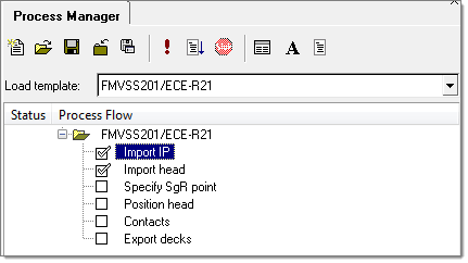
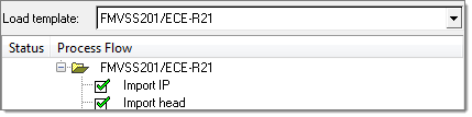
Once a step has been successfully completed, the check next to the panel name will turn green in color to indicate that it is completed.
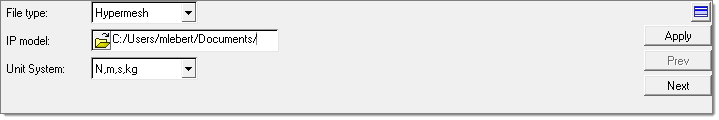
A panel, as shown below, appears to specify the IP model file path and import it.
The File type determines the input reader while importing the model. The supported file types are HyperMesh and RADIOSS. The full path to the IP model should be specified in the IP model field. Select the appropriate Unit System and click Apply to import the IP model. If the IP model is not in the same units as the selected unit system, a message will appear indicating that it is not the same. You have to manually change it to the correct unit system. |
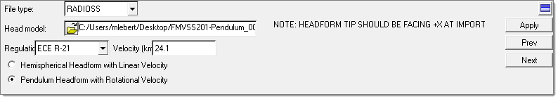
The next panel is used to specify the Head model file path and import it.
The File type determines the input reader while importing the model. The supported file types are HyperMesh and RADIOSS. The full path to the head model file should be specified in the Head model field. The regulations that are supported are FMVSS 201 and ECE R-21. The default Velocity for the FMVSS 201 regulation is 19.3 and for ECE R-21 it is 24.1, but you can change these values. For both of the regulation types, two types of headforms are supported; a hemisphere headform for linear velocity input and a pendulum headform with rotational velocity input. These headform types are available to support the various methods that customers use to perform the test. Click Apply to import the head model. |
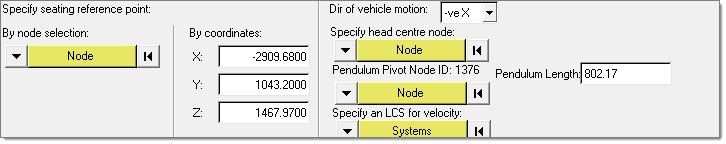
A panel, as shown below, appears to specify the seating reference point by selecting Node or specifying nodal coordinates and vehicle direction.
The Node selection is used to select the seating reference point from the model. The By coordinates field is used to specify the node using coordinates, if they are known.
For all modes, that is FMVSS 201, ECE-R21, hemisphere headform and pendulum headform setup, this point is used for zone marking. In addition for FMVSS 201 the seating reference point is used to calculate the pivot point in the case of pendulum and angles for FMVSS 201. Specify the direction of vehicle motion in the Dir of vehicle motion field. This can be either +veX or -veX. In the case of a pendulum model, you need to specify the head center node and pivot node to calculate the arm length and the pivot location. The calculated length is shown in the graphical user interface. This length is used to adjust the velocity for ECE-R21 mode. You can change the length, if desired. The manually entered length will be used to adjust the velocity. Click Apply to save the information. |
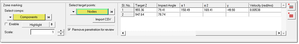
A panel, as shown below, appears to position the head at specified target points on IP.
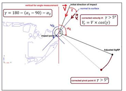
This image shows nomenclature for the angles displayed in the table for ECE-R21
Impact Angle: Angle between the vertical axis and the direction of impact. α1: Angle between the vertical axis, the pendulum arm set at the impact point, and adjusted SgRP. α2: Angle between the vertical angle and the normal to the surface at the target point. The options in the panel perform the following actions:
Csv file formatIf the setup was performed using HyperMesh and if the target points were manually selected on the IP, at the time of export these points are written out in the .csv file which can be imported later. If you have a .csv file generated from another tool you can import it into HyperMesh if it has the appropriate labels put in the header.
Perform the following steps:
|
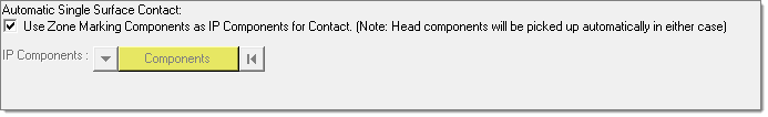
LS-DYNA user profileA panel, as shown below, is used to create contact definitions.
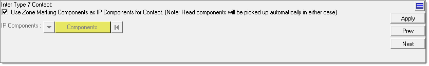
The Automatic Single Surface Contact is the type of contact to be created. It creates contact for a single surface so that it does not penetrate itself. After selecting the components click Apply to create the specified contacts. RADIOSS user profileA panel, as shown below, is used to create contact definitions.
For contact definition, a Type 7 symmetry contact is defined between the components that were selected for zone marking and the headform by default. If you want to manually provide the instrument panel components, uncheck the checkbox and the component selection will be enabled for manually selecting the components. Click Apply to create the specified contacts between the specified components. |
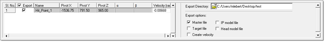
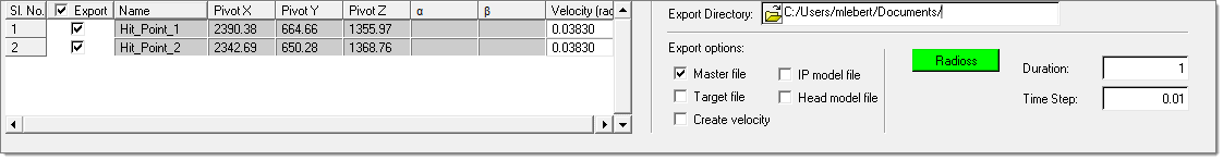
LS-DYNA user profileA panel, as shown below, appears to export decks for the selected target points for the selected solver.
The final information about each point is displayed in the table. The points to be exported must be selected. Optionally, the velocity can be modified here. Specify the path to the export directory in the Export Directory field. If it does not exist, it will be created as well as the sub folders and file structure. The files to be exported for the selected points must be selected in the Export options field. Click Apply to start the export process. RADIOSS user profileA panel, as shown below, appears to export decks for the selected target points for the selected solver.
The options in the panel perform the following actions:
Perform the following steps:
|