
Creating Geometry Data |

|

|

|

|
|
Creating Geometry Data |
|
|
|

|
Creating Geometry Data |
|
|
|
|
|
Creating Geometry Data |
|
|
|
|
If geometry is not available from a CAD system, you can create or edit geometry using the line and surface builders. The panels used in this process are listed below:
lines creation and editing panels |
||
|
Create lines in a variety of methods, including: from points, at tangents, and at the intersection of other geometry. |
|
|
Edit existing lines in a variety of methods such as combine, split, smooth, or extend. |
|
|
Circles |
Create circles or arcs. |
surfaces creation and editing panels |
||
|
Create surfaces from existing lines or nodes by different methods, such as spline, drag, or spin. |
|
|
Primitives |
Create standard shaped surfaces or solid entities, including squares, spheres, cones, and cylinders. |
|
Edit existing surfaces by trimming, extending, or shrinking. |
|
|
Edit existing surfaces by removing individual features such as holes or fillets. |
|
point/node creation and editing panels |
||
|
Create new nodes. Several methods are available. |
|
|
Add or remove nodes used only for geometry creation or editing. |
|
A NURBS (non-uniform rational B-spline) surface is a parametric surface defined by control points, knots and weights. The ruled, spline/filler, and drag/spin subpanels of the Surfaces panel can be used to create NURBS surfaces.
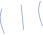
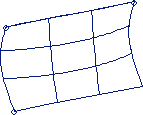
The spline option creates a surface through 3D lines. If you select a set of lines that do not form a closed loop, the disconnected lines will be connected with straight lines, and create a spline surface and/or mesh in the enclosed area. There is no limit on the number of lines used to create a mesh/surface.
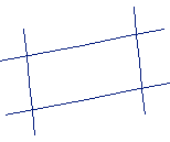
These lines form one path because they intersect at four points.
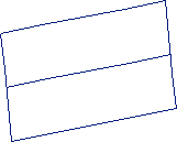
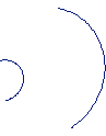
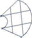
These lines form more than one path and cause an error.
The tolerance setting on the Options panel is used to determine the intersections between lines. If the tolerance is too small and an intersection cannot be found, an error is reported when you attempt to create the surface.
Lines that contain sharp edges can cause problems when you create a surface. These lines result in a more complex surface, which takes longer to create, and slows the automeshing process. These sharp edges are sometimes the result of data created on other CAD/CAM systems and brought in via a translator. These lines may need to be "smoothed" by using the Line Edit panel or replaced with a new, smooth, line by using the Lines panel.
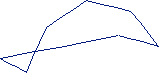
Creating a surface with these lines results in a relatively complex surface.
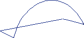
The "circular" shaped line has been replaced with a smooth line, which results
in a much simpler surface. In some cases the sharp edges are required to represent
the model and should not be smoothed.
The skin option can create a skinned surface through a set of lines.
Lines used to define a skinned surface.
A skinned surface created from the lines.
The ruled option can create a ruled surface between two lines.
Lines used to create a ruled surface.
A ruled surface created from the lines.
General Process for Building Models