This connection type is designed to simulate a bolted connection without the need for any holes in the adjoining shell parts.
The connection works by defining a projection diameter tolerance, two projection distance tolerances (L1 and L2) and a projection vector, which together determine which nodes will be considered for the connection.
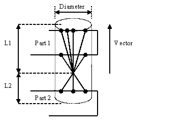
There is then a simple RBODY connection from the center reference node of the connection. There is also a secondary type that uses a spring between the RBODY ends; this spring length is user defined.
To create a cylinder bolt:
| 1. | In the Bolt panel, select the bolt location, components to connect, Num Layers, and Tolerance as normal. |
| 2. | For Type =, select cylinder rigid or cylinder spring. |
| 3. | Select a cylinder direction vector option: |
| • | dynamic vector: normal projection to the furthest link will be used as the direction of the cylinder bolt |
| • | use existing vector: the existing vector associated with the connector will be used as the direction of the cylinder bolt; if it is absent, the result is the same as the option above |
| • | define a new vector: define a new vector from the vector definition item as the direction of the cylinder bolt |
| 4. | Input diameter, L1,and L2 |
| • | If cylinder spring is selected, also specify Body length= . |
See Also:
Bolt panel


