Engineering Solutions

Editing Plates, Base Surfaces, and Collapsed Lines

Editing Plates, Base Surfaces, and Collapsed Lines

Previous topic Next topic Expand/collapse all hidden text  

Editing Plates, Base Surfaces, and Collapsed Lines

Previous topic Next topic JavaScript is required for expanding text JavaScript is required for the print function  

Plates, base surfaces, and collapsed lines on the midsurface can be modified using the iterim edit tools in the midsurface panel. The modifications you make to the midsurface using the iterim edit tools are not automatically applied. You must delete and re-extract the midsurface in the auto extraction subpanel to apply your changes.

hmtoggle_plus1greyEditing Plates

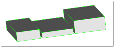
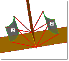
Plates are a group of surfaces in the model in which the middle surface will be inserted. Each plate has two sides: blue and green. The middle surface is inserted between the two sides of each plate. When you click show/edit all, surfaces are organized into components that reflect their plate type. To display the plates as per their component color, change the geometry display mode to Mixed on the Visualization toolbar.

When the automatic detection of plates is not correct, click show/edit all to manually edit plates.

Plate information will only created upon extracting midsurface using the offset+planes+sweeps and offset+planes methods.

Any changes made to the midsurface using the plate edit tools will not be visible until you click update within the same panel, or after you extract the midsurface using the offset+planes+sweeps or offset+planes methods.

1.In the edit plates subpanel, click show/edit all.
2.Using the single surface selector, select surfaces to create new plates from.
3.On the left side of the panel, select a type of plate to create.
4.Click new plate. A new plate is created out of the selected surfaces.
5.Continue modifying the midsurface, or click update to re-extract the midsurface.


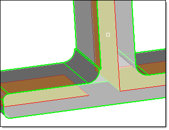
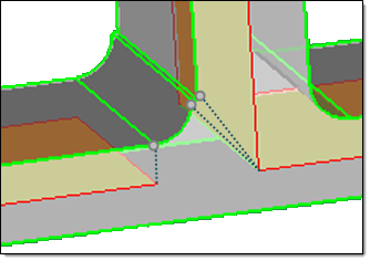
Transition surface provide more information to the algorithm regarding inserting surface where two regular plates are intersecting. An algorithm calculates how far intersecting plates can be extended based on the transition surface.

1.In the edit plates subpanel, click show/edit all.
2.Using the single surface selector, select surfaces.
3.Click transition surface. The selected surfaces are used as transition surfaces during midsurface extraction.
4.Continue modifying the midsurface, or click update to re-extract the midsurface.


1.In the edit plates subpanel, click show/edit all.
2.Using the single surface selector, select surfaces that you do not want to be considered trim surfaces.
3.Click not a trim surface. The selected surfaces are placed in the component, ^Not a trim surface.
4.Continue modifying the midsurface, or click update to re-extract the midsurface.

During midsurface extraction, the surfaces in the ^Not a trim surface component will be ignored.


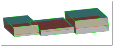
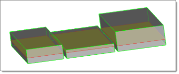
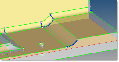
Each plate has two sides (blue and green) between which the midsurface is inserted. By default, the midsurface is generated by offsetting the green side of the plate.

1.In the edit plates subpanel, click show/edit all.
2.Using the single surface selector, select surfaces to switch the offset side.
3.Click switch sides.
4.Continue modifying the midsurface, or click update to re-extract the midsurface.

During midsurface extraction, the midsurface will be offset from the opposite side that it was originally offset from. If the midsurface was generated by offsetting the green side of the plate, the midsurface will now be generated by offsetting the new green side which was blue before using switch side.


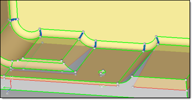
Plate edges act as trimming surfaces for all plate types, and are used to trim inserted midsurfaces.

1.In the edit plates subpanel, click show/edit all.
2.Using the single surface selector, select surfaces to serve as trimming surfaces.
3.Click plate edge.
4.Continue modifying the midsurface, or click update to re-extract the midsurface.

During midsurface extraction, the midsurface is trimmed using the surfaces you selected.


1.In the edit plates subpanel, click show/edit all.
2.Using the full plate selector, select plates to merge.
3.On the left side of the panel, select a new plate type to create.
4.Click merge plates. All of the selected plates are merged into a single plate.
5.Continue modifying the midsurface, or click update to re-extract the midsurface.


hmtoggle_plus1greyEditing Base Surfaces

In certain situations, you may need to extract a midsurface from multiple solids as if they were a single solid.

midsurface_base_surface_example

Normally, this would result in multiple midsurfaces, each one at the middle of the solid it was extracted from (and therefore not aligned with each other).

In the edit base surfaces subpanel you can specify a distance from the base surfaces of multiple solids, that you wish to treat as if they were continuous, to generate separate-but-aligned midsurfaces for during extraction.

You can create aligned midsurfaces for non-aligned solids, by selecting each solid and specifying its offset separately, using a different offset for each (you must know the exact dimensions of each solid to do this accurately).

midsurface_base_surface_nonaligned

If use base surfaces is disabled, new midsurfaces will not be generated at the specified distance from the selected base surfaces. The setup of the base surfaces that you modified will be retained for future use as long as you do not delete them.


1.Go to the edit base surfaces subpanel.
2.Select use base surfaces.
3.Using the surfs selector, select base surfaces.
Note:If both sides of a plate are selected as the base surface, the side which is used will be random.
4.In the distance to base field, specify a distance to create new midsurfaces from the selected base surfaces.
Note:If align steps (extraction options subpanel) and use base surfaces are both used for the same solids, then the base surface distance will overwrite the align steps distance.
5.Click add base.
6.Go to the auto extraction subpanel.
7.Click extract. The original midsurface is deleted and a new midsurface is generated. Separate-but-aligned midsurfaces are generated at the specified distance from the bases of the surfaces that you modified.

midsurface_base_surface_complete


hmtoggle_plus1greyEditing Collapsed Lines

Automatically extracted midsurfaces may include gaps, which are caused by a failure to correctly interpret relatively complex topology. In many cases, this can occur when a solid part has a fillet on one side but not on the other, or a fillet has a step or "ledge" at one end of its curve. In the image below, a gap in the midsurface is caused by a step in the fillet.

midsurface_rerun_auto_failed

The auto midsurface extraction tool attempts to determine where each point on the geometry should collapse to meet the generated midsurface. Errors occur when the extraction tool collapses points to the wrong corresponding locations on the midsurface. This often happens when the two end-points on a line collapse to separate points instead of to the same point.

In the image below, the curved lines on each fillet are correctly associated with each other.

midsurface_rerun_collapsed_example

In the image below, the step in the fillet caused the extraction tool to associate the two points at the end of the step's edge with each other and collapse (correctly) toward the T-joint of the midsurface, while the remaining points at the other ends of the curved lines were then incorrectly collapsed in a normal direction instead of to the same point.

midsurface_rerun_failed_pointcollapse

You can enable visualization settings to display point associations on the midsurface after extraction and manually define lines and line chains to establish the linkage between points that should collapse to the same location using the edit collapsed lines subpanel.

Pre-requisite: Reject the current midsurface.

1.Go to the edit collapsed lines subpanel.
2.Select allow rerun.
3.Set the switch to prepare for rerun.
4.Go to the auto extraction subpanel.
5.Click extract. The midsurface is extracted, and the lines that connect associated points are highlighted blue.

midsurface_rerun_prepare_example


Pre-requisite: Display point associations on the midsurface.

1.Go to the edit collapsed lines subpanel.
2.Set the switch to do rerun.
3.Activate the lines to collapse selector.
4.Select each line segment that you wish to collapse to a single point on the midsurface.
5.Click collapse. The selected line segments collapse and are highlighted light blue, indicating that they are new collapsed lines.

midsurface_rerun_editcollapsedlines

6.Go to the auto extraction subpanel. The collapsed lines that were automatically found during the initial midsurface extraction and the lines that you manually collapsed remain highlighted blue and flagged for collapse.
7.Click extract. The original midsurface is deleted and a new midsurface is generated using all of the lines that are flagged for collapse.
Note:If allow rerun is disabled or the allow rerun switch is set to no rerun or prepare for rerun, then the lines that you manually collapsed will not be used when a new midsurface is extracted.

midsurface_rerun_fixed


Pre-requisite: Display point associations on the midsurface.

1.Go to the edit collapsed lines subpanel.
2.Set the switch to do rerun.
3.Activate the lines to collapse selector.
4.Select collapsed lines to delete.
5.Click delete.


1.Go to the edit collapsed lines subpanel.
2.Set the switch to do rerun.
3.Activate the trim surfaces with cut line selector.
4.Select surfaces to trim.
5.Click drag a cut line.
6.Click where you wish the line to begin, then click one or more times where you wish the lines to either end or change direction.
7.Press ESC. The line is generated and any selected surfaces it crosses are trimmed.


See Also:

Extracting Midsurfaces

Midsurface Panel