In the Section browser, right-click and select Create > Shell Section or Solid Section from the context menu.
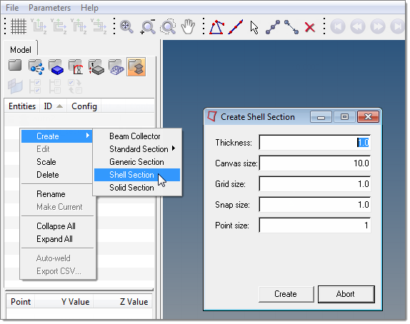
In the Create dialog, define the following:
| 1. | Thickness – This is the default thickness for each new part created. Part thicknesses can be edited later. |
| 2. | Canvas size – Sets the initial length and width of the sketching area. |
| 3. | Grid size – The default size of the background grids. This can be altered in the Parameters pull-down menu. |
| 4. | Snap size – While sketching, this is the smallest interval at which you can define a vertex by clicking. This is also the snap size while moving existing vertices. |
| 5. | Point Size - Controls the size of the vertices in the graphics area. Increasing the point size makes it easier to select an existing grid point when you are creating a part. |
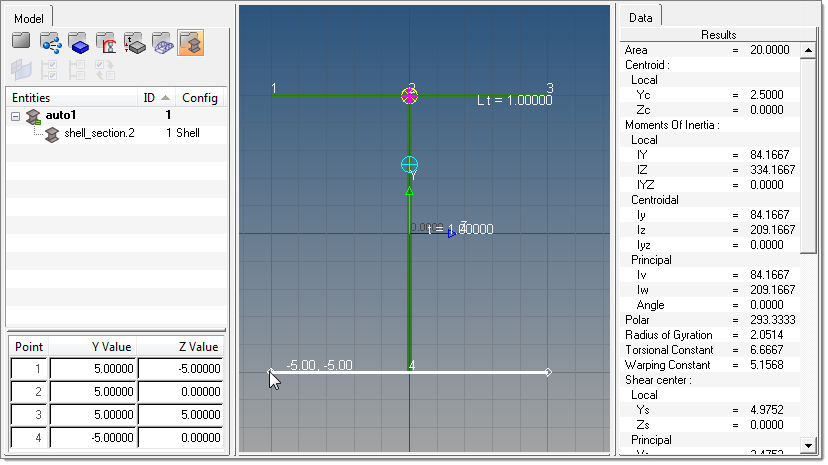
Once the defaults are set, the canvas will appear and you can start creating parts with the shell part / solid perimeter tool ( ). Once clicked, the button remains highlighted until you move the mouse off of the canvas.
| • | Left-click to create a new vertex. |
| • | Right-click to remove vertices in the reverse order they were created. |
| • | Once the part is complete, move the mouse off of the canvas to finalize it. |
Remember, each part has only one thickness, and it’s common to have a section with multiple connecting parts.
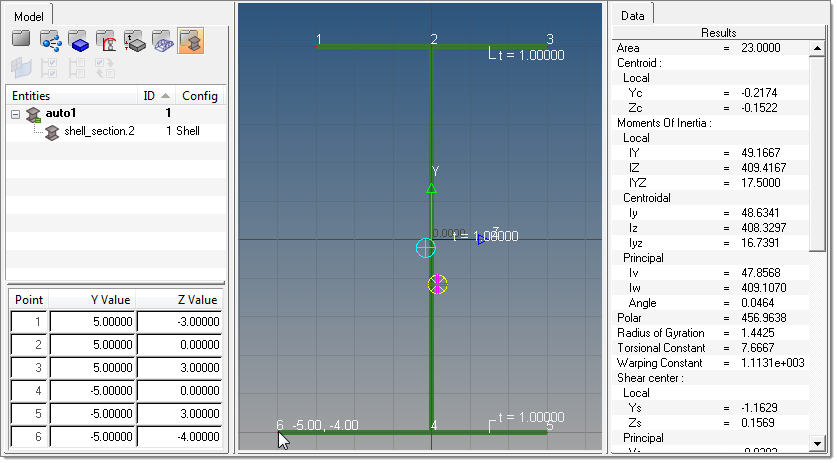
Another useful function on the HyperBeam toolbar is the Move vertex / Adjust Dimension tool ( ). This tool has two main uses, one of which is to click and drag vertices to snap points for shell and solid sections. The other is to adjust parameters such as shell thicknesses or standard section parameters.
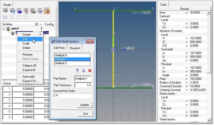
After the parts are created and assembled it is sometimes necessary to revise the connectivity or change the part thicknesses. This can be done in the part editor shown above. Each part is listed with its part name, thickness and connectivity, and as each part is selected it will highlight yellow on the canvas.
The connectivity order is simply the order in which the vertices are drawn for a given part. Remember to leave a space between each vertex when editing the connectivity order.
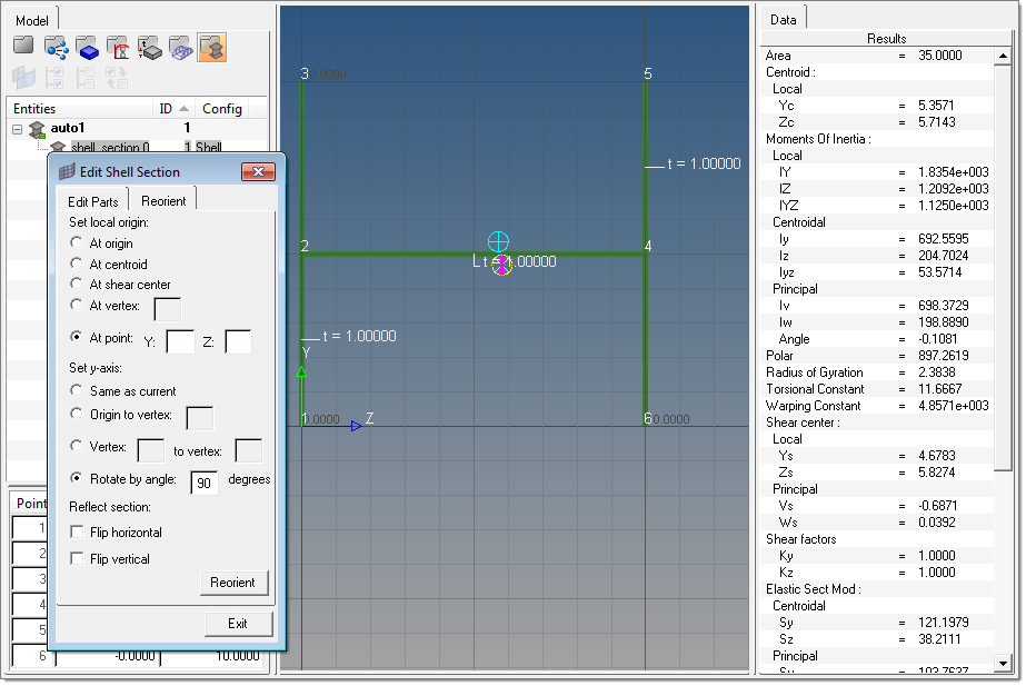
Another tool in the Edit shell section dialog is the Reorient tab. This allows you to redefine the local axis location and angle. This becomes useful when comparing HyperBeam shell section properties (results) to more rigidly-defined sections. Please note that changing the local axis in HyperBeam is not the same as using element offsets in a finite element model.
The same toolset can be applied to sketching solid sections as well. You can start by right-clicking the browser on the left hand side, creating a new solid section, and defining defaults for Canvas, Grid and Snap sizes.
The Shell part / Solid perimeter tool can now be used to trace the outline of a solid shape.
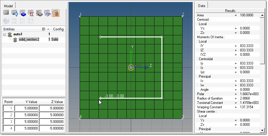
As before, once the outline is sketched, move the mouse out of the canvas area to finalize the part. Unlike shell sections, solid sections can only have one part defined, although the same tool can be used to sketch out a cavity within the solid section.
| Note: | Only one cavity can be defined per section. |
|
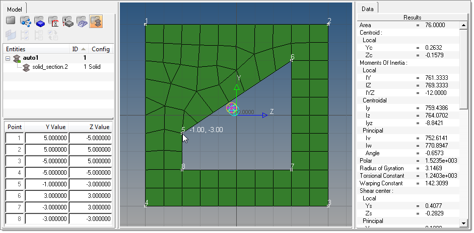
As before, the Move vertex / Adjust dimension tool can be used to move vertices of solid sections. Each vertex movement requires a remesh of the solid section, so take care when moving vertices of complicated parts.


