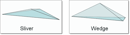
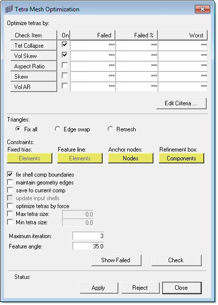
Aspect Ratio
|
The ratio of the longest edge of an element to its shortest edge.
|
Tet Collapse
|
Tetra collapse is calculated by the following procedure. At each of the four nodes of the tetra, the distance from the node to the opposite side of the element is divided by the square root of the area of the opposite side. The minimum value found is normalized by dividing it by 1.24, and then reported. As the tetra collapses, this value approaches 0.0. For a perfect tetra, this value is 1.0.
|
Vol Skew
|
Volumetric skew is calculated by the following procedure. A sphere is fit through the four nodes of the tetra. That sphere defines an ideally shaped equilateral tetra, whose volume is  . The actual volume of the tetra element is then calculated. . The actual volume of the tetra element is then calculated.
The element's volumetric skew is then (Videal -Vactual)/Videal. This measure will, normally, equal the skew measure from Tgrid, and equal 1 minus the equivalent check in Abaqus.
|
Skew
|
Skew applies to trias, so in this case it is applied to the faces of a tetrahedron.
In trias is calculated by finding the minimum angle between the vector from each node to the opposing mid-side and the vector between the two adjacent mid-sides at each node of the element. Ninety degrees minus the minimum angle found is reported as the skew.
|
Vol AR
|
Vol AR for tetrahedral elements is calculated using the following procedure: first it finds the longest edge of the tetrahedron, then it finds the shortest altitude of the tetrahedron. The element's Vol AR, then, is the length of the longest edge divided by the length of the shortest altitude. For other types of 3d element, the ratio of the longest to the shortest edge is reported.
|
Edit Criteria
|
Opens the Criteria and Parameter File Editor, from which you can change the element quality requirements.
|
Triangles
|
The 2-D triangles on the outermost surface of the tetrameshed volume, from which the initial tetramesh is derived. Multiple options for fixing exist:
| • | Fix all: nodes will be moved to improve tria quality, which will affect any tetras stemming from those trias. |
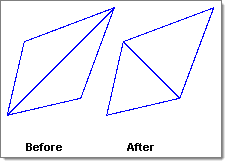
| • | Edge Swap: Pairs of triangles can have their edges swapped to create better tria elements: |
| • | Remesh: The current mesh will be discarded and a new mesh generated to fit the specified criteria. This usually produces the best results. |
|
Constraints
|
Constraints prevent the utility from altering nodes in specific groups of elements. Four types of constraint can be specified:
| • | Fixed Trias: click elements and then select trias on the screen that you wish to remain unchanged during optimization. Only applies during Edge Swap or Remesh. |
| • | Feature Line: click the elements button and then select 1D feature elements (if present) along one or more feature lines that you wish to preserve during optimization. These elements may be modified, but not in ways that alter the feature line. Only applies during Edge Swap or Remesh. |
| • | Anchor Nodes: click the button and then select nodes on the screen that you wish to remain unchanged; these nodes will not be moved during the optimization process. |
| • | Refinement Box: Only elements inside of the refinement box will be optimized; the remainder will not. When you click Components, a temporary panel opens and you can select the refinement box component. |
|
Fix shell comp boundaries
|
When unchecked, nodes on the edges of components will not be moved.
|
Maintain geometry edges
|
Nodes on the edges of geometric entities will not be moved.
|
Save to current comp
|
The resulting fixed mesh will be added to the current component. If this option is left unchecked, the results are saved to the same component they originated in.
|
Update input shells
|
Updates the shell elements attached to modified tetra elements. Only applies during Edge Swap or Remesh.
|
Optimize tetras by force
|
Adds a sophisticated node insertion algorithm to the optimization process. This typically yields higher element quality in the resulting mesh, but can also increase computation time.
|
Max tetra size
|
Threshold for the maximum tetra element edge length during mesh optimization.
|
Min tetra size
|
Threshold for the minimum tetra element edge length during mesh optimization.
|
Maximum Iteration
|
The tool will make this number of passes to fix elements; the more iterations, the better the results are likely to be, but each iteration takes some amount of time depending on the mesh complexity. Use smaller numbers to limit the amount of time spent, or larger numbers to achieve better end results.
|
Feature Angle
|
If the angle between the normals of two adjacent shell elements exceeds this value, the corresponding edge is treated as a feature edge and is preserved durong the optimization process.
|
Show Failed
|
Isolates only the failed elements in the graphics area.
|
Check
|
Examine the mesh and count the number of bad elements, according to the criteria supplied (Jacobian, Volume Skew, and so on.) The results display in the Status area.
|
Apply
|
Begin the fix process. The mesh is scanned and the program will try to fix as many elements as it can in accordance with the specified settings and criteria.
You can abort the fix attempt early by clicking holding down the right-mouse button.
| Note: | There can be a significant delay before Engineering Solutions finishes its current fix attempts and stops processing. |
|
Reject
|
If the results of the fixes are unacceptable, click this to revert the mesh to its pre-fixed state.
| Note: | You can only undo one fix operation this way--you cannot "back up" more than one step! |
|
Close
|
Close the utility.
|