Use the Metadata to CAE tool to take metadata generated as part of the CAD import process, and use it to setup CAE models. To access this tool, click Geometry > Metadata to CAE from the menu bar.
| 1. | From the Create field, select Part Names. |
| 2. | From the From field, select Components. |
| 3. | From the Metadata field, select a specific metadata name. A list of entities is generated. |
| 4. | In the table, select entities to operate on. |
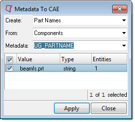
| 5. | Click Apply. The new names are taken as the values of the specified metadata attached to each selected component. If there are duplicate names, an incremental name is generated. |
|
| 1. | From the Create field, select Part IDs. |
| 2. | From the From field, select Components. |
| 3. | From the Metadata field, select a specific metadata name. A list of entities is generated. |
| 4. | In the table, select entities to operate on. |
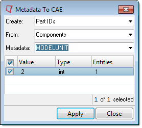
| 5. | Click Apply. The new IDs are taken as the values of the specified metadata attached to each selected component. If there are duplicate IDs, the entities will not be renumbered. |
|
| 1. | From the Create field, select Regions. |
| 2. | From the From field, select Points, Lines, Surfaces, or Solids. |
| 3. | From the Metadata field, select a specific metadata name. A list of entities is generated. |
| 4. | In the table, select entities to create regions from. |
|
| 1. | From the Create field, select Connectors. |
| 2. | From the From field, select Points. |
| 3. | From the Metadata field, select a specific metadata name. A list of points is generated. |
| 4. | In the table, select the points to create spot connectors from. |
| 5. | Click Apply. Spot connectors are created from the selected points using components as links based on proximity. By default, HyperMesh uses two links. You can modify and/or realize the connectors using the Connector browser or connector panels. |
|
| 1. | From the Create field, select Connectors. |
| 2. | From the From field, select Lines. |
| 3. | From the Metadata field, select a specific metadata name. A list of lines is generated. |
| 4. | In the table, select the lines to create seam connectors from. |
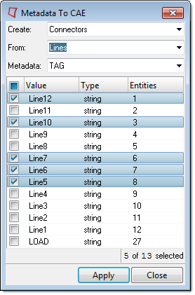
| 5. | Click Apply. Seam connectors are created from selected lines using components as links based on proximity. By default, HyperMesh uses a spacing of 1.0. You can modify and/or realize the connectors using the Connector browser or connector panels. |
|
| 1. | From the Create field, select Connectors. |
| 2. | From the From field, select Surfaces. |
| 3. | From the Metadata field, select a specific metadata name. A list of surfaces is generated. |
| 4. | In the table, select the surfaces to create area connectors from. |
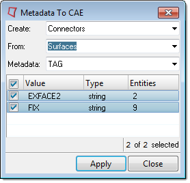
| 5. | Click Apply. Area connectors are created from selected surfaces using components as links based on proximity. You can modify and/or realize the connectors using the Connector browser or connector panels. By default, a quad mesh with an element size of 10.0 is used. |
|


