Entities
Engineering Solutions is architected around entities and solver interfaces. Entities can have none or multiple card images associated to them. Card images are defined within a solver interface template and allow for creation, editing, and deletion of a solver card within a model. Entities contain two types of data; data names and attributes. Data names are a part of the entity data structure itself and are available to all instantiations of the entity regardless if the entity has an associated card image or not. Attributes are additional data, defined in a solver interface template, which are necessary to store solver specific data for a card image associated with an entity. Entities can be subdivided into five major groups; Collectors, Collected Entities, Named Entities, Optimization Entities, and Morphing Entities. Collectors are named organizational containers for Collected Entities. An example of a Collector is the component collector which collects points, lines, surface, solids, elements, and connectors for model organization purposes. Collected Entities are nameless entities which must reside within one, and only one, collector. Examples of collected entities include points, lines, surfaces, solids, elements, and connectors, which are collected by a component collector. Named entities are entities which are given a name but are not collected or organized into containers. Examples of named entities include materials and properties. Optimization entities and morphing entities are special groupings of named entities for optimization and morphing specific data respectively.
Include Files
Collectors and Collected Entities
Named Entities
Optimization Entities
Morphing Entities
Solver Interfaces
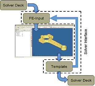
A solver interface is made up of a template and an FE-input reader. A template defines the mapping between solver cards and Engineering Solutions entities, the attributes necessary to store data for solver cards, and the format which the solver cards are exported from a database. FE-input readers perform the function of reading solver decks and importing solver cards into the appropriate Engineering Solutions entities with the appropriate card images, data names, and attributes set as defined by the template. Furthermore, FE-input readers require template attribute definitions to perform their tasks. A schematic of the Engineering Solutions solver interface architecture is shown below.
Templates
An example of the interaction between Engineering Solutions entities and templates with data names and attributes for a OptiStruct MAT1 card is given below. The OptiStruct MAT1 card has the following definition:
(1)
|
(2)
|
(3)
|
(4)
|
(5)
|
(6)
|
(7)
|
(8)
|
(9)
|
(10)
|
MAT1
|
MID
|
E
|
G
|
NU
|
RHO
|
A
|
TREF
|
GE
|
|
|
ST
|
SC
|
SS
|
|
|
|
|
|
|
The Engineering Solutions material named entity has data names of name and ID. Therefore the template would also have to define attributes for E, G, NU, RHO, A, TREF, GE, ST, SC, and SS in order to completely define and store the OptiStruct MAT1 solver card within a Engineering Solutions material named entity with a MAT1 card image. Templates define attributes using the *defineattribute() command.
In order to associate the OptiStruct MAT1 solver card to the Engineering Solutions material named entity with a MAT1 card image the template would contain a *materials(MAT1) definition block to define this association. Within the *materials(MAT1) definition block a MAT1 card image would be defined using a *beginmenu() definition block . This *beginmenu() definition block is read every time a materials named entity with a MAT1 card image is card edited using the Card Editor within Engineering Solutions. In addition, an export format for the OptiStruct MAT1 solver card would be defined using a *format() definition block within the *materials(MAT1) definition block. This *format() definition block is read every time an export of the database is requested which contains a materials named entity with a MAT1 card image. For more information on templates see Custom Templates in the HyperMesh Reference Manual.
Loading a template
Templates are necessary to tell Engineering Solutions how entities behave and what data are associated with them. Engineering Solutions cannot be used efficiently until a template is loaded. Templates are loaded into Engineering Solutions using the Global panel. The Global panel can be accessed using the 'g' key. Once a template is loaded into Engineering Solutions, it can be used to create, edit, card edit, and delete entities with card images which are defined within the template. The example template code can be found in [Install Directory]\hm\examples\templates.
Creating and Card Editing Entities
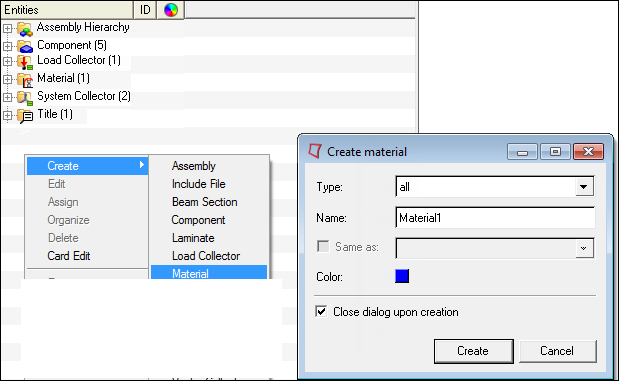
Engineering Solutions is now ready to create, edit, card edit, and delete material entities with a MAT1 card image. The Model browser can be used to create and card edit a material entity with a MAT1 card image. Within the Model browser, right click to bring up the context sensitive menu. Select Create > Material to display the Create material dialog. Enter information as shown to create a material named entity called Aluminum with a MAT1 card image.
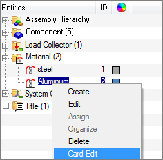
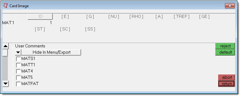
Now that a material entity with a MAT1 card image, named Aluminum, has been created it can be card edited to enter the remaining attributes that were defined for the MAT1 card image in the template. Using the Model browser, left click the Aluminum material entity to select it, then right click right on the entity to bring up the context sensitive menu associated with that entity. On the context sensitive menu select Card Edit to open the Card Editor for the Aluminum material entity and enter data for the attributes associated with the MAT1 card image as shown. Clicking return to close the Card Editor saves the data entered for the attributes on the entity. These are the basic operations in Engineering Solutions for creating and card editing entities with card images.
Exporting a Database as a Solver Deck
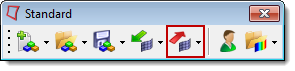
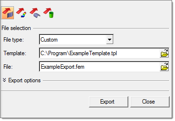
Now that a material entity with a MAT1 card image exists in the database, the database can be exported as a solver deck. The example template code defined the export format for material entities with MAT1 card images using the *format() definition block within the *materials(MAT1) definition block. To export a database as a solver deck, click the Export Solver Deck icon on the Standard toolbar to bring up the Export tab. On the Export tab define:
| • | File type: Custom (For a custom template. This will automatically be set if you are using user profiles in Engineering Solutions.) |
| • | Template: Select the template file you saved. This will automatically be set if you are using user profiles in Engineering Solutions. |
| • | File: Enter a file name to contain the exported solver deck. |
Click Export to perform the export of the database as a solver deck.
The solver deck exported above is shown below. Notice that the file contains a single MAT1 solver card with the same data as the data entered on the MAT1 card image of the material named entity, Aluminum, as this is the only entity in the database. Also notice that the solver deck is exported in 8 character field widths as this is what was defined in the *format() definition block within the *materials(MAT1) definition block.
Example Exported Solver Deck ([Install Directory]\hm\examples\feinput\ExampleExport.fem)
MAT1 11.00E+070.0 0.33 0.101 1.20E-050.0 0.0
60000.0 0.0 0.0
FE-Input, Importing a Solver Deck into a Database
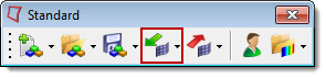
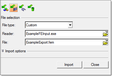
The role of an FE-input reader within a solver interface is to read solver decks and import each solver card into the appropriate Engineering Solutions entity with the appropriate card image, data names, and attributes defined by the template. FE-input readers are C/C++ code written using the hm.lib and hmin.lib libraries as the API for creating entities in the database. This code can be copied and compiled with any ANSI C++ complier using hmlib.h and hminlib.h header files and hm.lib and hmin.lib libraries. See the notes section below for location of header files, libraries, and example code. For more information on FE-input readers see Custom Readers in the HyperMesh Reference Manual. To import a solver deck into the database, click the Import Solver Deck icon on the Standard toolbar to bring up the Import tab. On the Import tab define:
| • | File type: Custom (For customer FE-input readers. This will automatically be set if you are using user profiles in Engineering Solutions.) |
| • | Reader: select the ExampleFEInput reader executable compiled with below code. This will automatically be set if you are using user profiles in Engineering Solutions. |
| • | File: enter a file name that contains the solver deck. |
Click Import to perform the import of the solver deck into a Engineering Solutions database.
| Note: | Templates for Engineering Solutions supported solver interfaces are located in [Install Directory]\templates\feoutput. |
| • | FE-input readers for Engineering Solutions supported solver interfaces are located in [Install Directory]\io\model_readers\feinput\bin\[Platform] |
| • | Macro files and Tcl/Tk scripts for Engineering Solutions supported solver interfaces are located in [Install Directory]\hm\scripts\[Solver Interface] |
| • | HMLIB.H and HMINLIB.H can be found in [Install Directory]\hm\include |
| • | HM.LIB and HMIN.LIB can be found in [Install Directory]\hm\lib\[Platform] |
| • | The Example Templates can be found in [Install Directory]\hm\examples\templates |
| • | The Example FE-Input readers can be found in [Install Directory]\hm\examples\feinput |
|
See Also:
Browsers
Collectors and Collected Entities
Named Entities
Morphing Entities
Optimization Entities


