Geometry Cleanup |

|

|

|

|
|
Geometry Cleanup |
|
|
|

|
Geometry Cleanup |
|
|
|
|
|
Geometry Cleanup |
|
|
|
|
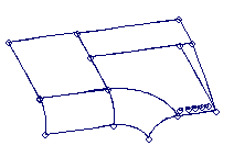
When designers create CAD geometry, their priorities are different from those of analysts trying to use the data. A single smooth surface is typically split into smaller patches, each a separate mathematical face. The juncture between two surfaces often contains gaps, overlaps, or other misalignments.
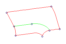
To make the geometry more appropriate for meshing, analysts need to combine a number of faces into a single smooth surface. This allows the elements to be created on the entire region at once, and prevents unnecessary artificial or accidental edges from being present in the final mesh.
The Quick Edit, Edge Edit, Point Edit, and Autocleanup panels contain tools to help you prepare surface geometry for meshing.
|
|
|
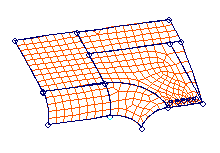
The initial CAD geometry often contains gaps, misalignments, or pinholes.These features can distort the elements or |
||
|
|
|
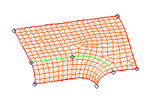
With the tools of the geometry cleanup panels, you can close the gaps between surfaces, combine surfaces into large meshing regions, and eliminate pinholes. Using the simpler, cleaner geometry, you can easily build a much better mesh. |
||
General Process for Building Models